
Pulverized coal burner and boiler having same

A pulverized coal burner, pulverized coal technology, applied in the direction of burners, burners burning powder fuel, using multiple fuels, etc., to achieve good high temperature resistance and thermal shock resistance, good high temperature resistance and heat resistance Shock resistance, avoiding the effect of high temperature corrosion problems

Active Publication Date: 2011-04-27
YANTAI LONGYUAN POWER TECH
View PDF0 Cites 4 Cited by
  • Summary
  • Abstract
  • Description
  • Claims
  • Application Information

AI Technical Summary

Problems solved by technology

However, prior art burners cannot meet these requirements

Method used


Image

  • Pulverized coal burner and boiler having same
  • Pulverized coal burner and boiler having same
  • Pulverized coal burner and boiler having same

Examples


Embodiment Construction

[0038] The technical solution provided by the present invention will be described in detail below in conjunction with the accompanying drawings. The description in this section is only an exemplary and explanatory description, and should not have any limitation on the protection scope of the present invention.

[0039] It should be noted that in this section, the axial direction is the direction consistent with the flow direction of the pulverized coal in the internal combustion chamber, and the horizontal direction is the direction perpendicular to the axial direction; and the direction of the pulverized coal flow is taken as a reference, and the position near the inlet of the internal combustion chamber is the front. The position far away from the inlet of the internal combustion chamber is rear.

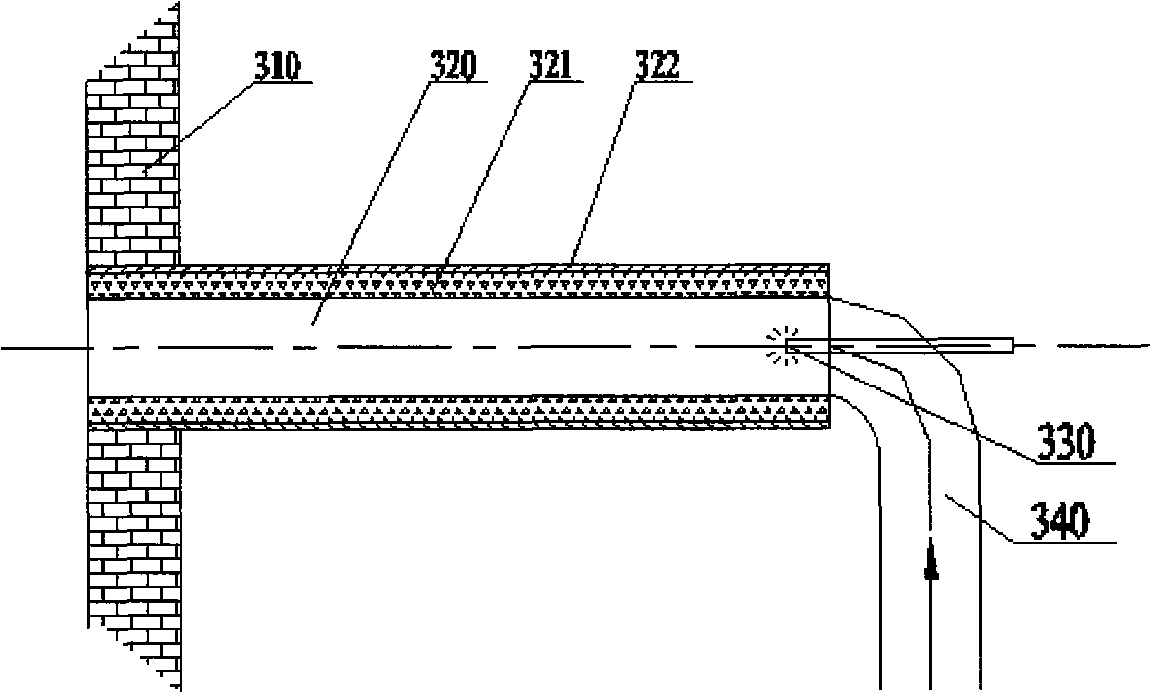
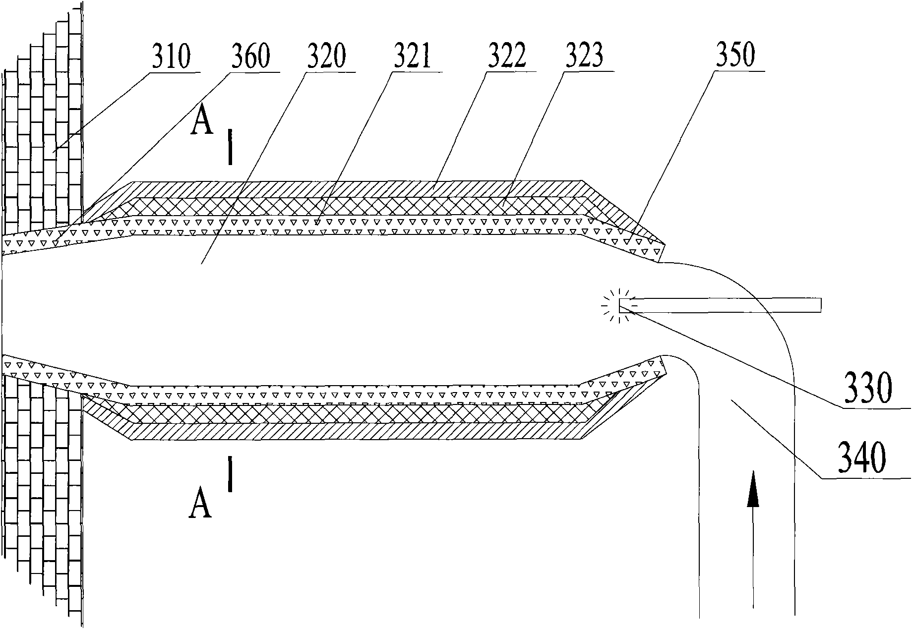
[0040] figure 2 This illustrates the axial cross-sectional structure of the pulverized coal burner provided in the first embodiment of the present invention. The pulverized coal burne...


PUM


Abstract

The invention discloses a pulverized coal burner and a boiler having the same. The pulverized coal burner comprises a heat source and an internal-combustion chamber for keeping the preset excess air coefficient of an internal pulverized coal air flow, wherein the heat source is positioned in the combustion chamber, and the internal-combustion chamber has an inlet and an outlet; and the heat source can light pulverized coal in the internal-combustion chamber and make the pulverized coal undergo reducing burning in the internal-combustion chamber; and the internal-combustion chamber comprises ametal outer cylinder and a ceramic liner. The ceramic material for making the liner of the pulverized coal burner has excellent high-temperature performance, and can retain corresponding mechanical performance under a continuous high-temperature condition; and the ceramic material has high thermal-insulation effect and can keep a higher temperature in the internal-combustion chamber of the pulverized coal burner.

Description

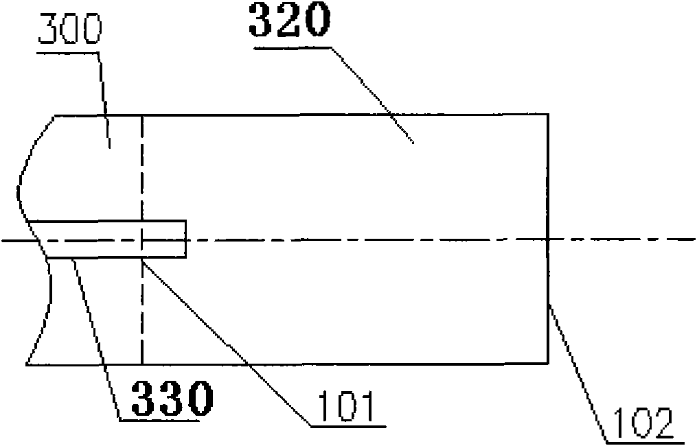
Technical field [0001] The invention relates to a combustion equipment, in particular to a pulverized coal burner, and also to a boiler with the pulverized coal burner. Background technique [0002] The applicant provided a pulverized coal burner in another patent application entitled "A pulverized coal burner and a boiler with the pulverized coal burner". Please refer to figure 1 The figure shows the structure of the pulverized coal burner provided by the above invention. The pulverized coal burner includes a heat source 330 and an internal combustion chamber 320. The internal combustion chamber 320 has an inlet 101 and an outlet 102. The internal combustion chamber 320 forms a suitable space to maintain the internal pulverized coal airflow with a predetermined excess air coefficient. The inlet 101 of the internal combustion chamber 320 communicates with the primary air pulverized coal pipeline, and the pulverized coal airflow enters the internal combustion chamber 320 through t...

Claims


Application Information

Patent Timeline
Patent Type & Authority Applications(China)
IPC IPC(8): F23D1/00F23C5/08
Inventor 王雨勃龚泽儒程昌业
Owner YANTAI LONGYUAN POWER TECH
Learn More