Processing-control device, laser processing device and laser processing system

A technology for controlling devices and processing positions, applied in general control systems, control/regulation systems, program control, etc., can solve problems such as poor processing and achieve the effect of reducing poor processing

Active Publication Date: 2011-04-27
MITSUBISHI ELECTRIC CORP
View PDF6 Cites 7 Cited by
  • Summary
  • Abstract
  • Description
  • Claims
  • Application Information

AI Technical Summary

Problems solved by technology

Therefore, for the part that is not actually perpendicular to the surface, the floor thickness increases according to the amount of inclination of the processing nozzle direction relative to the workpiece, so there is a problem that it is easy to cause poor processing.

Method used


Image

  • Processing-control device, laser processing device and laser processing system
  • Processing-control device, laser processing device and laser processing system
  • Processing-control device, laser processing device and laser processing system

Examples


Embodiment approach

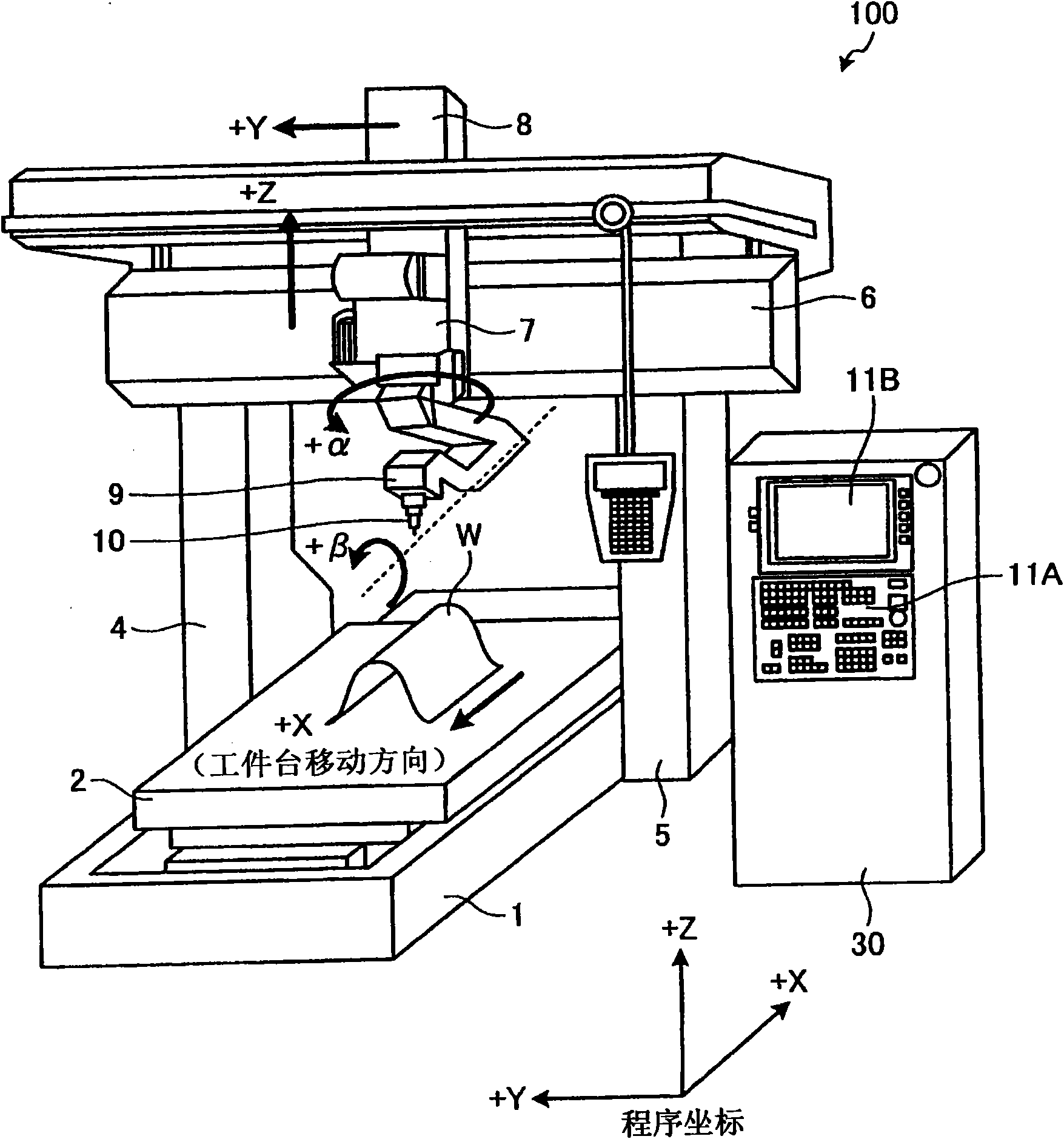
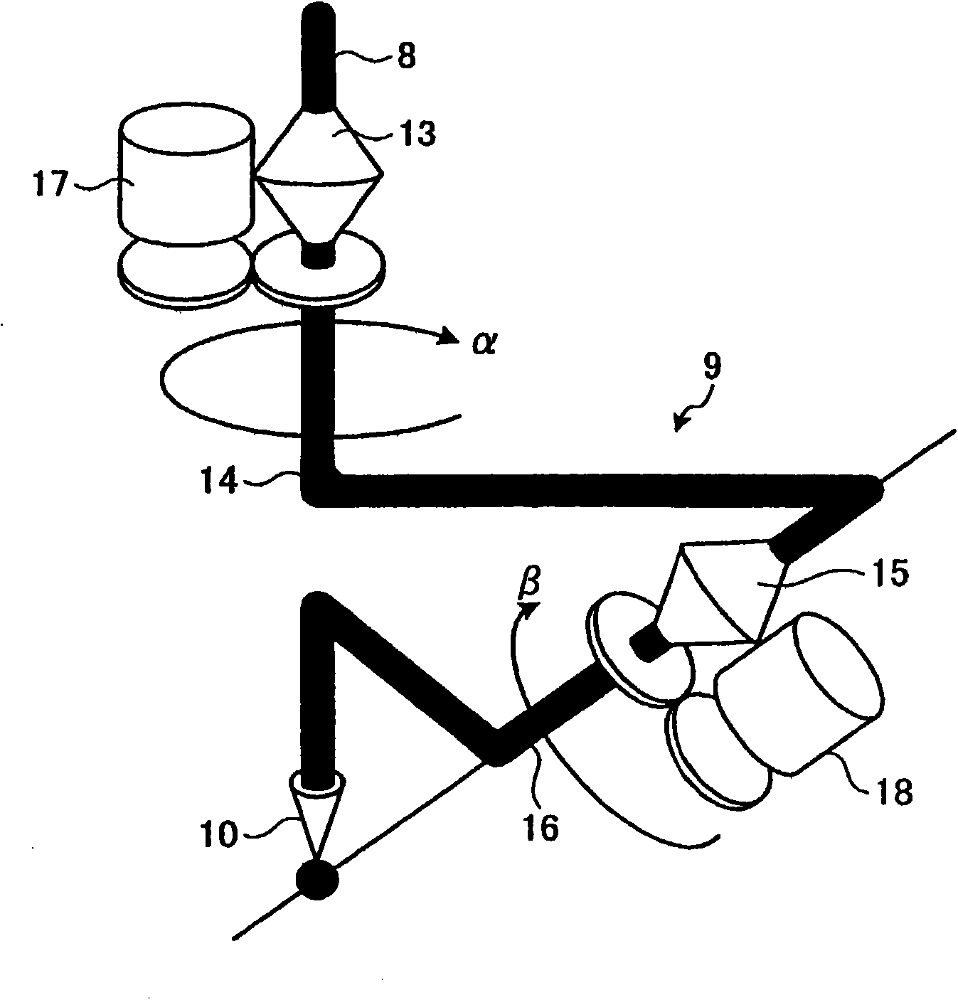
[0022] figure 1 It is a configuration diagram showing a three-dimensional laser processing machine according to an embodiment of the present invention. exist figure 1 In , a configuration example of the three-dimensional laser processing machine 100 is shown in a perspective view. The three-dimensional laser processing machine 100 sets the movement of the machining head 9 at each indicated point based on NC data 101A described later and the angle of the workpiece W relative to the machining nozzle 10 at each indicated point (the machining nozzle angle θ described later). speed (moving speed d described later). Then, three-dimensional laser processing of the workpiece W is performed while moving the processing head 9 at the moving speed d set for each indicated point.

[0023] The three-dimensional laser processing machine 100 has: a workpiece table 2, which can be moved along the X-axis direction and is arranged on the base 1; a transverse guide rail 6, which is horizontall...


PUM


Abstract

The invention provides a processing-control device, which can set appropriate moving speed of a processing head in a short time and reduce unqualified workpieces during process. The processing-control device which controls the three-dimensional laser processing of workpieces through laser irradiation comprises a moving speed setting part (33), which sets the moving speed of a processing head corresponding to the angle of a processing position for each processing position based on the angle formed between the surface of a processing position on a workpiece and the direction of the processing tip of a processing head; and a control indicating part (35), outputs control indication for a workpiece based on the moving speed set to control the three-dimensional laser process.

Description

technical field [0001] The invention relates to a processing control device, a laser processing device and a laser processing system for processing and controlling a workpiece according to a processing angle. Background technique [0002] A three-dimensional laser processing machine basically performs laser processing by irradiating laser light perpendicularly to the surface of a workpiece. In such a three-dimensional laser processing machine, it is necessary to set the direction of the processing nozzle (incident angle of the laser beam) in an appropriate direction with respect to the workpiece at each indication point showing the processing position, and to move the processing head at an appropriate The speed moves while processing. [0003] For example, there is a three-dimensional laser processing machine which has a speed setting function as means for setting the moving speed of a processing head, and calculates the moving speed based on the moving amount of each axis ...

Claims


Application Information

Patent Timeline
Patent Type & Authority Applications(China)
IPC IPC(8): G05B19/4097B23K26/08B23K26/00G05B19/42
Inventor 迎友则
Owner MITSUBISHI ELECTRIC CORP
Why Eureka
Try Eureka