
Permanent magnet brushless moment motor with double stators

A permanent magnet brushless and torque motor technology, which is applied in the direction of electrical components, electromechanical devices, magnetic circuit static parts, etc., can solve the problems of high precision and high torque density, reduction of motor torque coefficient, motor volume and quality Large and other problems, to achieve the effect of larger output torque, increased torque density, and elimination of cogging torque ripple

Inactive Publication Date: 2011-04-27
BEIHANG UNIV
View PDF4 Cites 11 Cited by
  • Summary
  • Abstract
  • Description
  • Claims
  • Application Information

AI Technical Summary

Problems solved by technology

According to the calculation formula of torque motor output torque, on the basis of a certain axial length of the motor, the output torque is proportional to the air gap magnetic density, coil current and winding coil turns, and after using the coreless stator, the motor air The gap flux density and the number of winding turns are all limited, so that the output torque of the motor is reduced, the torque coefficient of the motor is reduced, and the volume and mass of the motor are larger when the same torque is output.
Due to the above defects, the existing permanent magnet brushless torque motors are difficult to meet the requirements of high precision and high torque density at the same time

Method used


Image

  • Permanent magnet brushless moment motor with double stators
  • Permanent magnet brushless moment motor with double stators
  • Permanent magnet brushless moment motor with double stators

Examples


Embodiment Construction

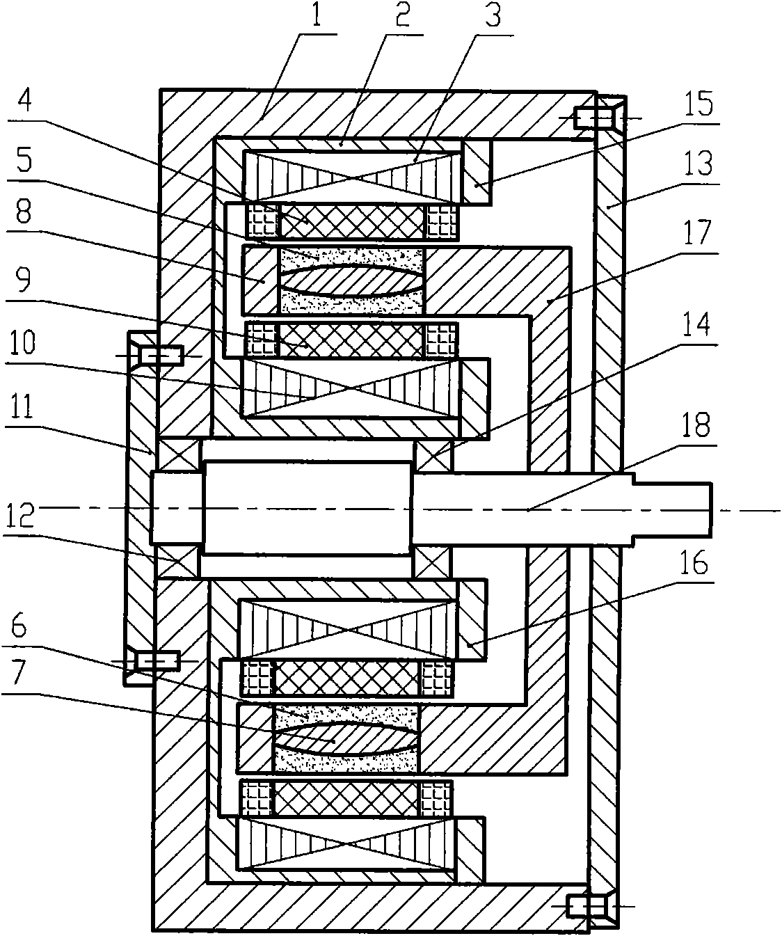
[0019] Such as figure 1 The shown double-stator permanent magnet brushless torque motor of the present invention consists of a housing 1, a sleeve 2, an outer stator core 3, an outer stator cup 4, a rotor outer magnet 5, a rotor inner magnet 6, a rotor core 7, Rotor retaining ring 8, inner stator cup 9, inner stator core 10, left end cover 11, left bearing 12, right end cover 13, right bearing 14, outer stator retaining ring 15, inner stator retaining ring 16, rotor connecting cylinder 17, rotor shaft 18; the inner side of the rotor core 7 is closely connected to the rotor inner layer magnetic steel 6, and the outer side is closely connected to the rotor outer layer magnetic steel 5, the three together form the rotor assembly with the rotor retaining ring 8 and the rotor connecting cylinder 17, the left side of the rotor core 7 Fixed by the rotor retaining ring 8, the right side of the rotor core 7 is connected to the rotor shaft 18 through the rotor connecting cylinder 17; th...


PUM


Abstract

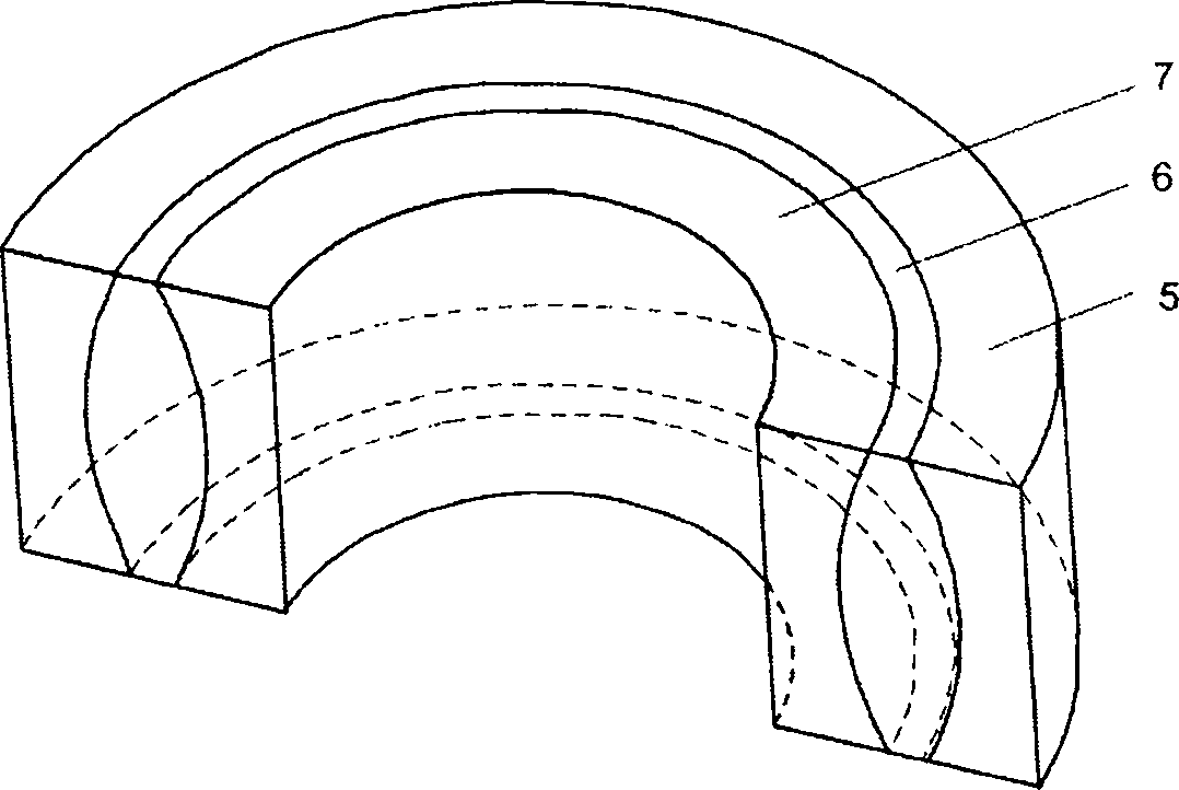
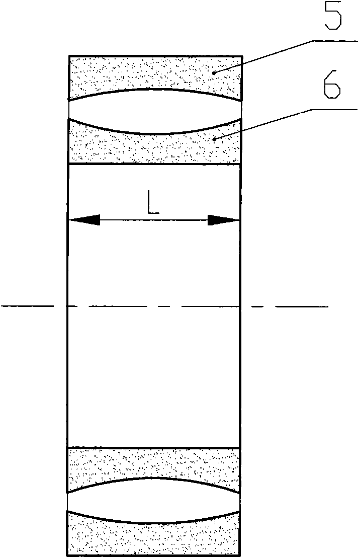
The invention discloses a permanent magnet brushless moment motor with double stators, mainly comprising a rotor shaft, an inner stator core, an inner stator cup, an outer stator core, an outer stator cup, a rotor core, rotor inner magnetic steel and rotor outer magnetic steel, wherein the rotor inner magnetic steel and the rotor outer magnetic steel are in a structure with a thin middle part and two thick ends along the axial direction; the rotor inner magnetic steel, the rotor outer magnetic steel and the rotor core jointly form a rotor assembly arranged between the inner stator cup and the outer stator cup; the inner stator cup and the outer stator cup are respectively fixedly connected with the inner stator core and the outer stator core; and the inner stator core and the outer stator core are connected to a main case through sleeves. The unequal thickness design of the rotor inner magnetic steel and the rotor outer magnetic steel in the invention compensates the influence of brow leakage on axial air gap flux density distribution and ensures the uniform axial distribution of the air gap flux density; coils of an inner stator winding and an outer stator winding jointly form the coils of a motor winding, the serial connection turn number of windings of each phase is increased to ensure that the moment coefficient of a motor becomes large, thereby increasing the moment density and reducing the volume of the motor.

Description

technical field [0001] The invention relates to a permanent magnet brushless torque motor, especially a double-stator cogging-free torque motor with small torque ripple and high torque density, which belongs to the field of motors and is suitable for low power consumption and high torque occasions, especially for It is suitable for occasions that require high output torque density. Background technique [0002] At present, direct drive motors with high precision and high torque density have become a hot spot in the development of permanent magnet motors. It is important to increase the torque density of motors and reduce the torque ripple of permanent magnet motors. In the traditional permanent magnet brushless torque motor, due to the existence of the stator cogging, the cogging torque and tooth harmonics will be generated when the rotor rotates, which will cause the torque to pulsate and generate a certain loss, which will further affect the motor output. Torque accuracy ...

Claims


Application Information

Patent Timeline
IPC IPC(8): H02K16/04H02K1/12H02K1/27
Inventor 房建成王春娥孙津济王曦杜国华
Owner BEIHANG UNIV
Learn More