Maximum Doppler frequency shift estimation method and device

A Doppler frequency shift and maximum technology, which is applied in the field of estimation method and device of maximum Doppler frequency shift, can solve the problem that the mobile speed of the terminal cannot be truly reflected, and achieve the effect of performance improvement

Active Publication Date: 2011-04-27
ZTE CORP
View PDF3 Cites 10 Cited by
  • Summary
  • Abstract
  • Description
  • Claims
  • Application Information

AI Technical Summary

Problems solved by technology

[0027] The main purpose of the present invention is to provide a method and device for estimating the maximum Doppler frequency shift, to at least solve the problem that the above-mentioned existing estimation methods cannot truly reflect the moving speed of the terminal

Method used


Image

  • Maximum Doppler frequency shift estimation method and device
  • Maximum Doppler frequency shift estimation method and device
  • Maximum Doppler frequency shift estimation method and device

Examples


Embodiment 1

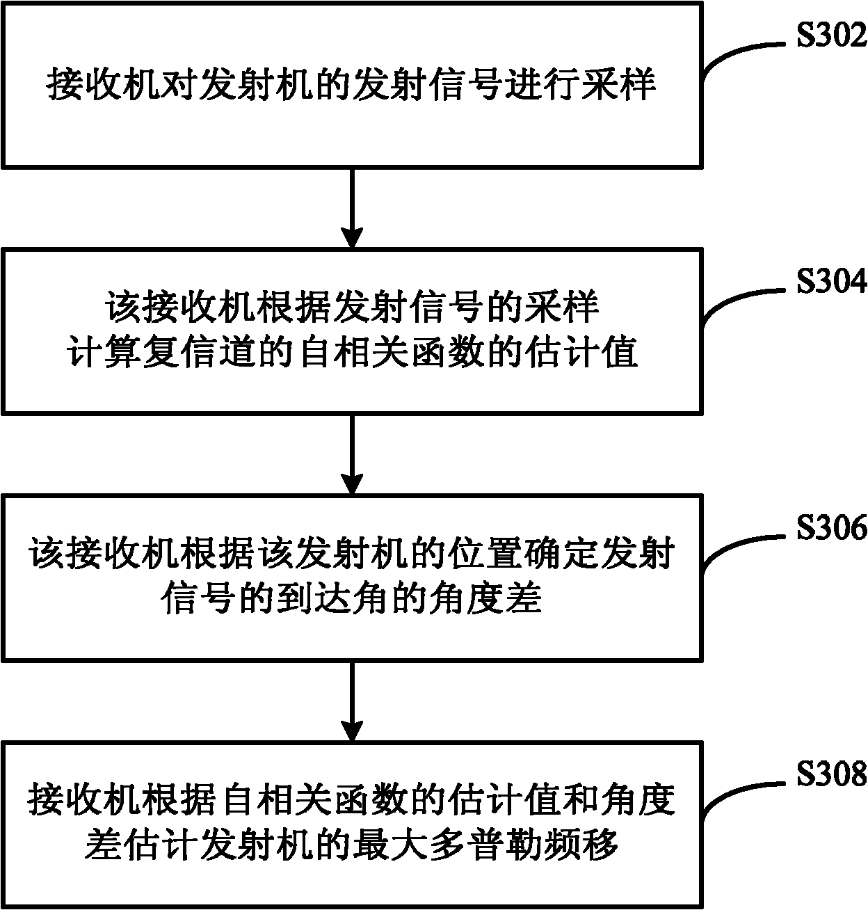
[0041] image 3 A flowchart showing a method for estimating a maximum Doppler frequency shift according to an embodiment of the present invention, the method includes the following steps:

[0042] Step S302, the receiver samples the transmitted signal of the transmitter;

[0043] Step S304, the receiver calculates the estimated value of the autocorrelation function of the complex channel according to the sampling of the transmitted signal;

[0044] For example, to compute an estimate of the autocorrelation function of a complex channel

[0045] Among them, T S is the sampling period;

[0046] T=k·T s , k is a positive integer;

[0047] h() is the channel response function, h H () is the transposition of h();

[0048] n is the sampling moment, n=1, 2, ..., L-1, L is the number of sampling points;

[0049] m for is the time at 0 o'clock.

[0050] Step S306, the receiver determines the angular difference of the arrival angle of the transmitted signal according to the...

Embodiment 2

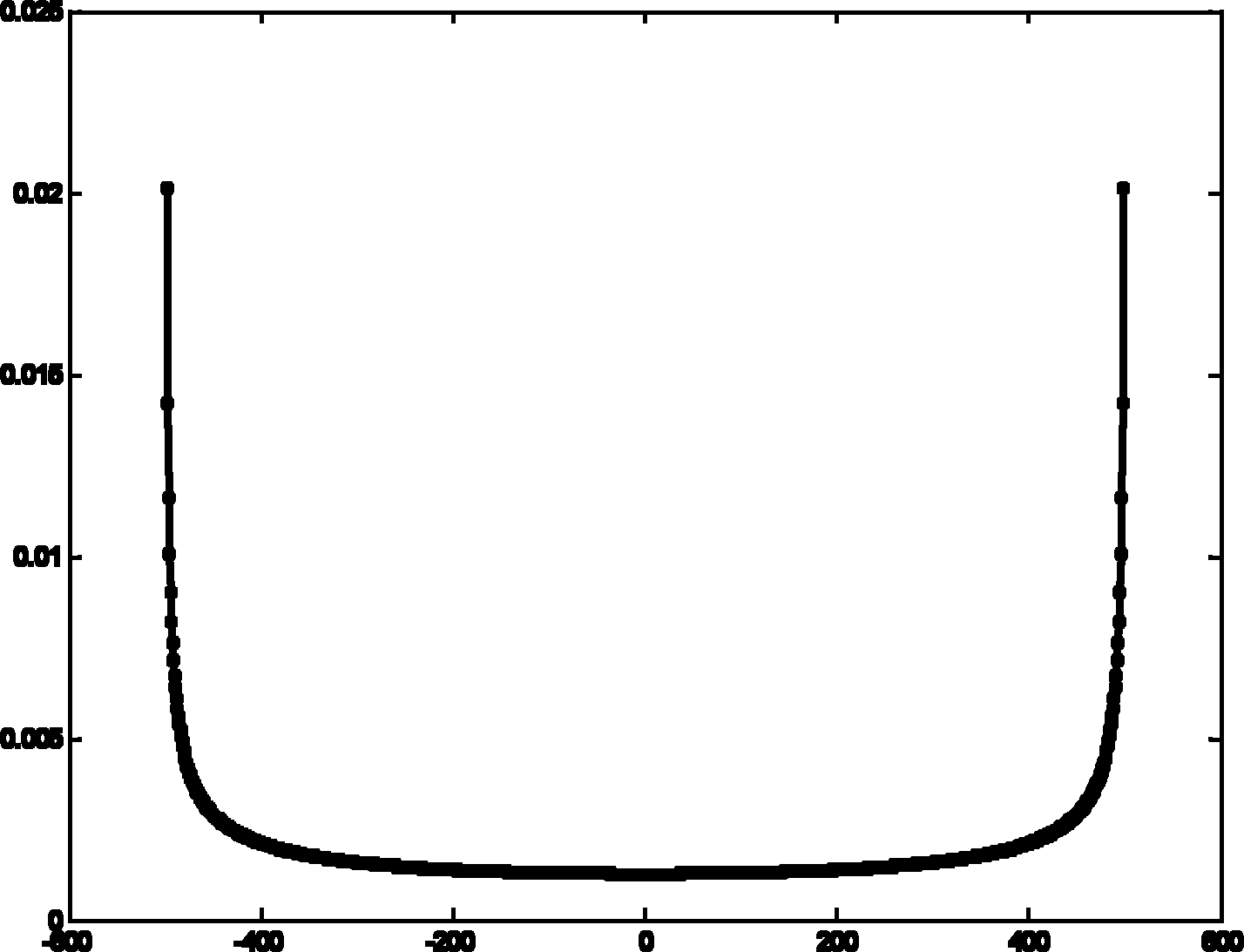
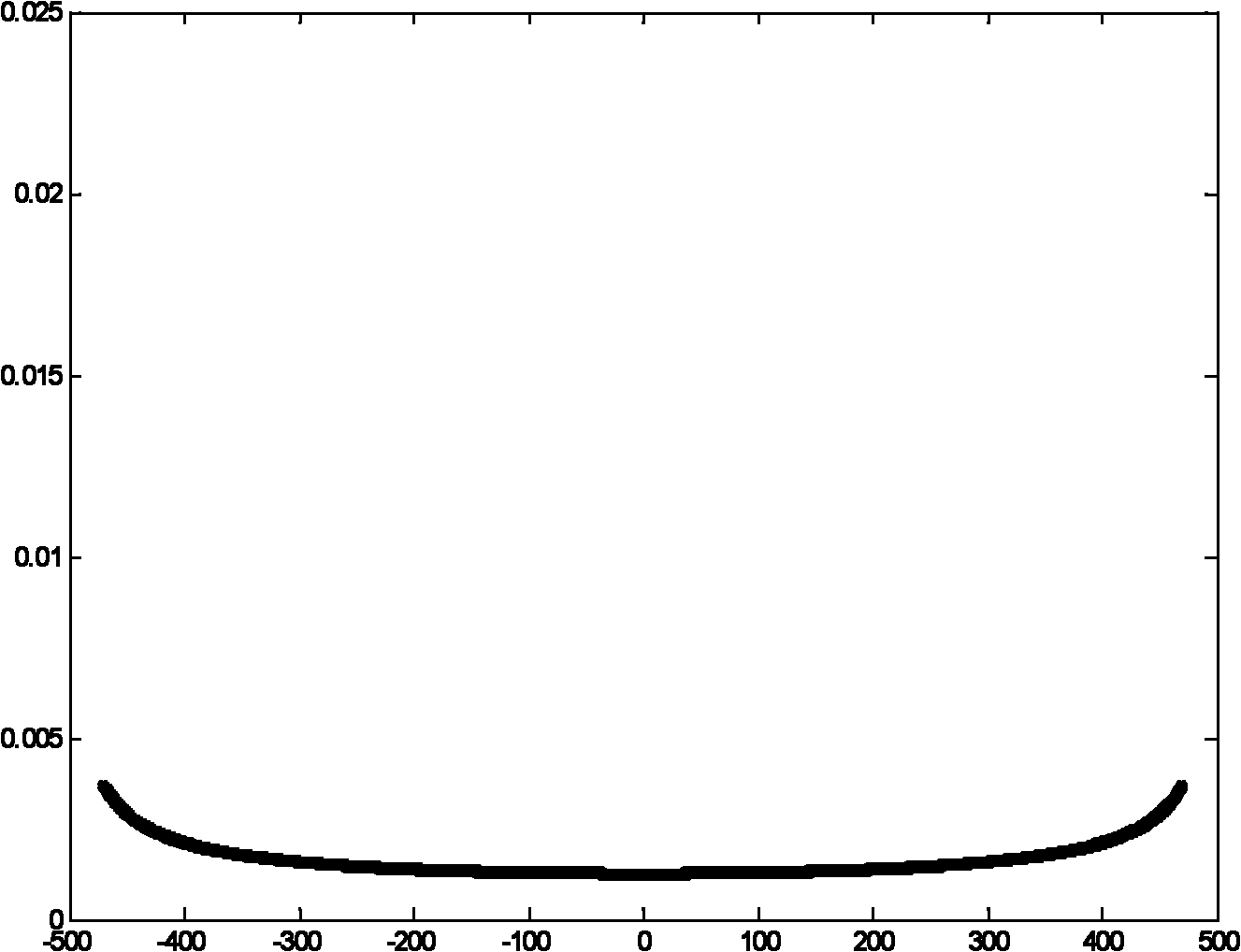
[0066] This embodiment takes Figure 4 The single-antenna system shown is taken as an example for illustration. The schematic diagram of the incident wave reaching the receiving end in this system is shown in Figure 4 As shown, among them, due to the lack of scatterers in this system, the multipath signal cannot reach the range of (-π, π) uniformly at the receiving end. At this time, the difference between the ideal channel autocorrelation function and the actual autocorrelation function is very large, so when using the autocorrelation function to estimate the maximum Doppler frequency shift, the actual autocorrelation function needs to be corrected.

[0067] First calculate the estimated value of the autocorrelation function of the complex channel from the received signal of the receiver: Wherein, the meaning of each parameter is the same as that of Embodiment 1, and will not be described in detail here. For example: T is the sampling point period T s Integer multiples o...

Embodiment 3

[0082] This embodiment takes Figure 5 The multi-antenna system shown is taken as an example to illustrate, and the schematic diagram of the incident wave reaching the receiving end is as follows Figure 5 As shown; In a multi-antenna system, when the relative movement direction of the transmitter and the receiver is the vertical direction, the relative movement cannot be measured. Such as Figure 5 As shown, where the incident wave arriving at antenna M is considered to be the transmitter moving vertically relative to the antenna, resulting in a Doppler of 0, and the incident wave arriving at antenna 1, the movement of the transmitter relative to the antenna is not between antenna 1 and transmitter In the vertical direction of the connection line, there is Doppler, so the maximum Doppler frequency shift can be measured through antenna 1.

[0083] In this embodiment, two antennas in the multi-antenna are used to estimate the maximum Doppler frequency shift corresponding to t...


PUM


Abstract

The invention provides a maximum Doppler frequency shift estimation method and device. The method comprises the steps: a receiver samples a transmitting signal of a transmitter; the receiver calculates the estimated value of an autocorrelation function of a complex channel according to the sampling result of the transmitting signal; the receiver determines the angle difference of an arrival angle of the transmitting signal according to the position of the transmitter; and the receiver estimates the maximum Doppler frequency shift of the transmitter according to the estimated value of the autocorrelation function and the angle difference. The invention solves the problem that the existing estimation method can not really reflect the travelling speed of a terminal, thus being beneficial to improving switching and load balancing performances in a wireless mobile communication system.

Description

technical field [0001] The present invention relates to the communication field, in particular to a method and device for estimating the maximum Doppler frequency shift. Background technique [0002] In a wireless communication system that uses base stations and / or relay stations for wireless resource management, the scheduling and allocation of system resources are all performed by the base station and / or relay stations, for example, the base station schedules and allocates resources for downlink transmission and resources for terminals for uplink transmission Wait. [0003] When a transmitter (e.g., a terminal) moves relative to a receiver (e.g., a base station), the received signal experiences the well-known Doppler effect, whereby the amplitude of the received signal will scale with the speed at which the receiver and transmitter are moving relative to each other. Scale changes. In the radio resource management process, the maximum Doppler frequency shift is a very imp...

Claims


Application Information

Patent Timeline
Patent Type & Authority Applications(China)
IPC IPC(8): H04L25/02H04L25/03
CPCH04L25/022H04L25/0222H04L25/0252
Inventor 关艳峰陈宪明鲁照华
Owner ZTE CORP
Why Eureka
Try Eureka