
Wound protection device for negative pressure drainage wound surface restoration system

A technology of wound repair and negative pressure drainage, applied in wound drainage devices, medical science, bandages, etc., can solve the problems of secondary pollution, high medical cost patients, etc., achieve pain relief, convenient and quick treatment, and reduce costs and pains Effect

Inactive Publication Date: 2011-05-04
刘柏
View PDF8 Cites 0 Cited by
  • Summary
  • Abstract
  • Description
  • Claims
  • Application Information

AI Technical Summary

Problems solved by technology

[0003] However, the structure of the existing wound-protecting materials is only to insert a porous drainage tube into the sponge body. One end of the drainage tube is closed in the sponge body, and the other end extends out of the sponge body to connect with the negative pressure source. The problem with this structure is: the wound surface Under the negative pressure of the negative pressure source, the exudate or liquefied necrotic tissue enters the drainage tube through the hole of the spongy body and the hole of the drainage tube. Once the drainage tube is blocked, there is no good solution: ① or by reinjecting the liquid Soak the blockage, but at the same time, it will also make the exudate or liquefied necrotic tissue that has entered the drainage tube re-enter the wound surface to cause secondary pollution; ②When the blockage cannot be eliminated, the whole set of products can only be replaced, resulting in high medical costs and pain for patients 3. have again, if need inject medicine to wound surface, also can only inject through the open end of drainage tube, also can make the exudate or liquefied necrotic tissue that has entered drainage tube re-enter wound surface again and cause secondary pollution

Method used


Image

  • Wound protection device for negative pressure drainage wound surface restoration system
  • Wound protection device for negative pressure drainage wound surface restoration system
  • Wound protection device for negative pressure drainage wound surface restoration system

Examples


Embodiment Construction

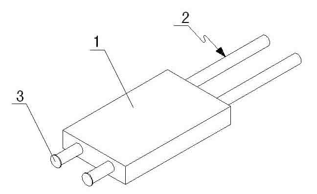
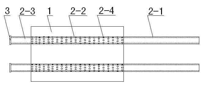
[0012] Such as Figure 1 ~ Figure 4 As shown, the wound protection device for the negative pressure drainage wound repair system is composed of a sponge body (1), a drainage tube (2) and a tube passer (4).

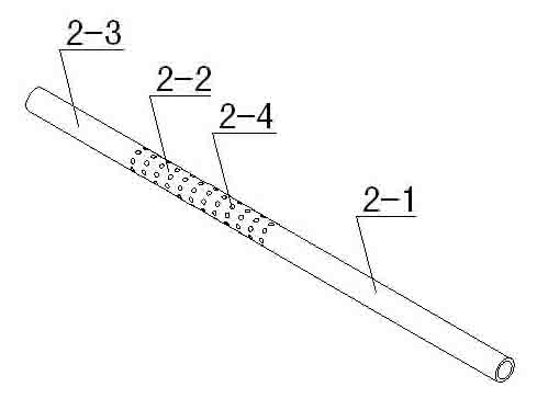
[0013] The drainage tube (2) is divided into a drainage area (2-1), a suction area (2-2) and a dredging injection area (2-3). The suction area (2-2) is provided with several holes (2-4), The drainage tube (2) passes through the cavernous body (1), the suction area (2-2) is placed in the cavernous body (1), and the drainage area (2-1) and dredging injection area (2-3) extend out of the sponge respectively The two ends of the body (1), dredge the end of the injection area (2-3) and connect the sealing plug (3).

[0014] When necessary, insert the pipe passer (4) into the drainage tube (2) from the end of the dredging injection area (3-3).


PUM


Abstract

The invention relates to a wound protection device for a negative pressure drainage wound surface restoration system, wherein the used technical solution is that the device comprises a sponge body and a drain tube; the device is characterized in that the drain tube is divided into a drain area, a suction area and a dredging medicine injection area; the suction area is provided with a plurality of holes; the drain tube passes through the sponge body; the suction area is arranged in the sponge body; the drain area and dredging medicine injection area respectively stretch out of two to ends of the sponge body; and the end part of the dredging medicine injection area is connected with a seal plug. The wound protection device for a negative pressure drainage wound surface restoration system is characterized in that the device is provided with a tube connector. The device is simple in structure, easy for the operation of blockage dredging and easy for medicine injection of the wound surface without causing secondary pollution to the wound surface.

Description

technical field [0001] The invention belongs to the field of medical instruments, and in particular relates to a wound protection device in a negative pressure drainage wound repair system for repairing soft tissue or skin defects in orthopedic surgery or hand and foot surgery. Background technique [0002] In orthopedic surgery or hand and foot surgery, it is necessary to treat the wound before repairing large-area soft tissue infection, defect and necrosis, exposed steel plate, exposed bone, exposed tendon, and open fracture with soft tissue defect. The traditional method is to use The manual method is to disinfect and change the dressing on the wound every day, so that every time the dressing is changed, it will bring great pain to the patient, it will be difficult for the medical staff to handle it, and it will also cause secondary pollution of the wound. Therefore, in 1992, Dr. Fleischman of ULM University in Germany pioneered the negative pressure drainage technology. ...

Claims


Application Information

Patent Timeline
IPC IPC(8): A61M27/00A61M35/00A61F13/00
Inventor 刘柏
Owner 刘柏
Learn More