Electric vehicle and charging method thereof

A technology of electric vehicles and charging methods, which is applied in the direction of electric vehicles, current collectors, vehicle components, etc., and can solve problems that affect the normal operation of supercapacitor buses, cannot be popularized and used in large quantities, and the use efficiency of charging stations is not high.

Inactive Publication Date: 2011-05-04
周良勇
View PDF1 Cites 12 Cited by
  • Summary
  • Abstract
  • Description
  • Claims
  • Application Information

AI Technical Summary

Problems solved by technology

The disadvantage of this supercapacitor bus is that it needs to stop and charge at the station, even if there is no passenger getting on and off at the station, it will stop and charge, and it will stop for tens of seconds (usually about 30 seconds, and the passenger's parking and waiting psychology The endurance time is generally 20 seconds) to ensure the charging time; when multiple buses enter the station at the same time, it is necessary to wait for the front car to drive away before the supercapacitor bus behind can drive to the charging position for charging; this station-style charging The station can only charge the supercapacitor bus passing through the station, and other electric vehicles cannot be used (because other electric vehicles cannot drive to the station, otherwise it will affect the normal operation of the supercapacitor bus; use supercapacitors to store electric energy Because the height of the car is not high enough, it is impossible to use the high-hanging charging power contact line on the site to charge), which results in the inefficiency of the use of the charging site and the high cost of the entire system.
Although supercapacitor buses have been put into commercial operation in 2006, due to the above-ment...

Method used


Image

  • Electric vehicle and charging method thereof
  • Electric vehicle and charging method thereof
  • Electric vehicle and charging method thereof

Examples


Embodiment Construction

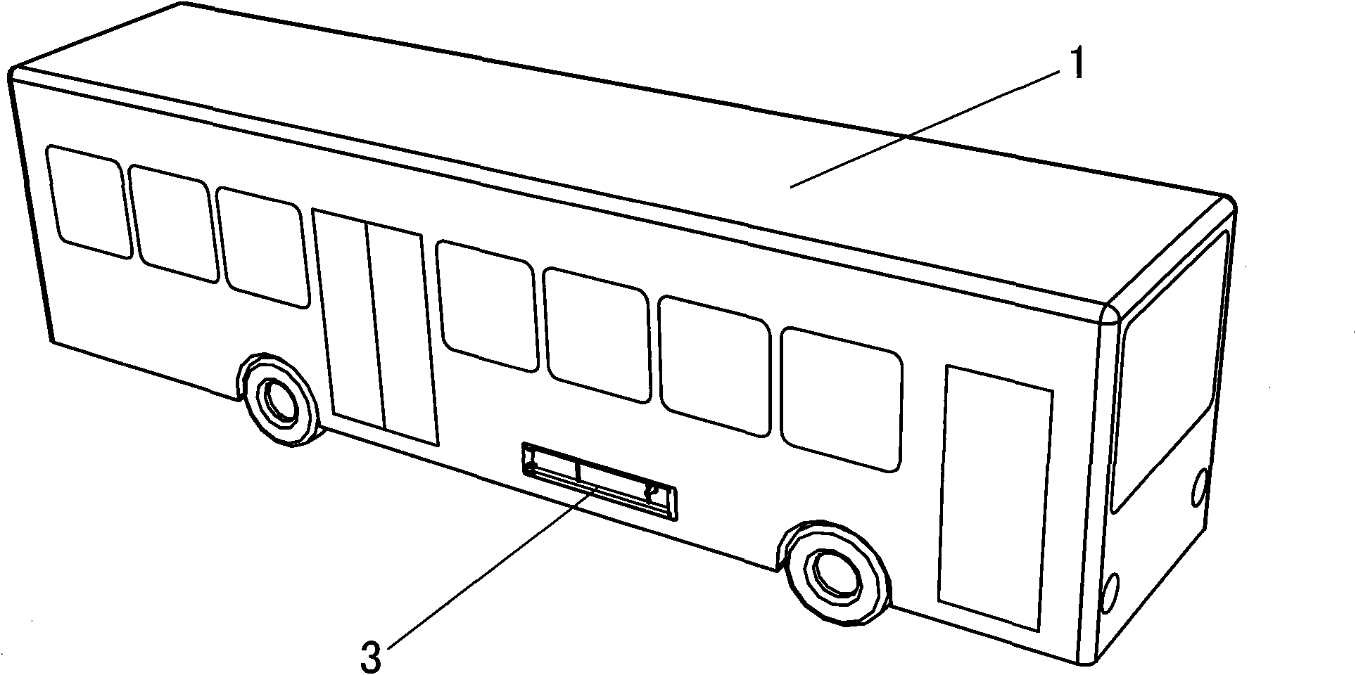
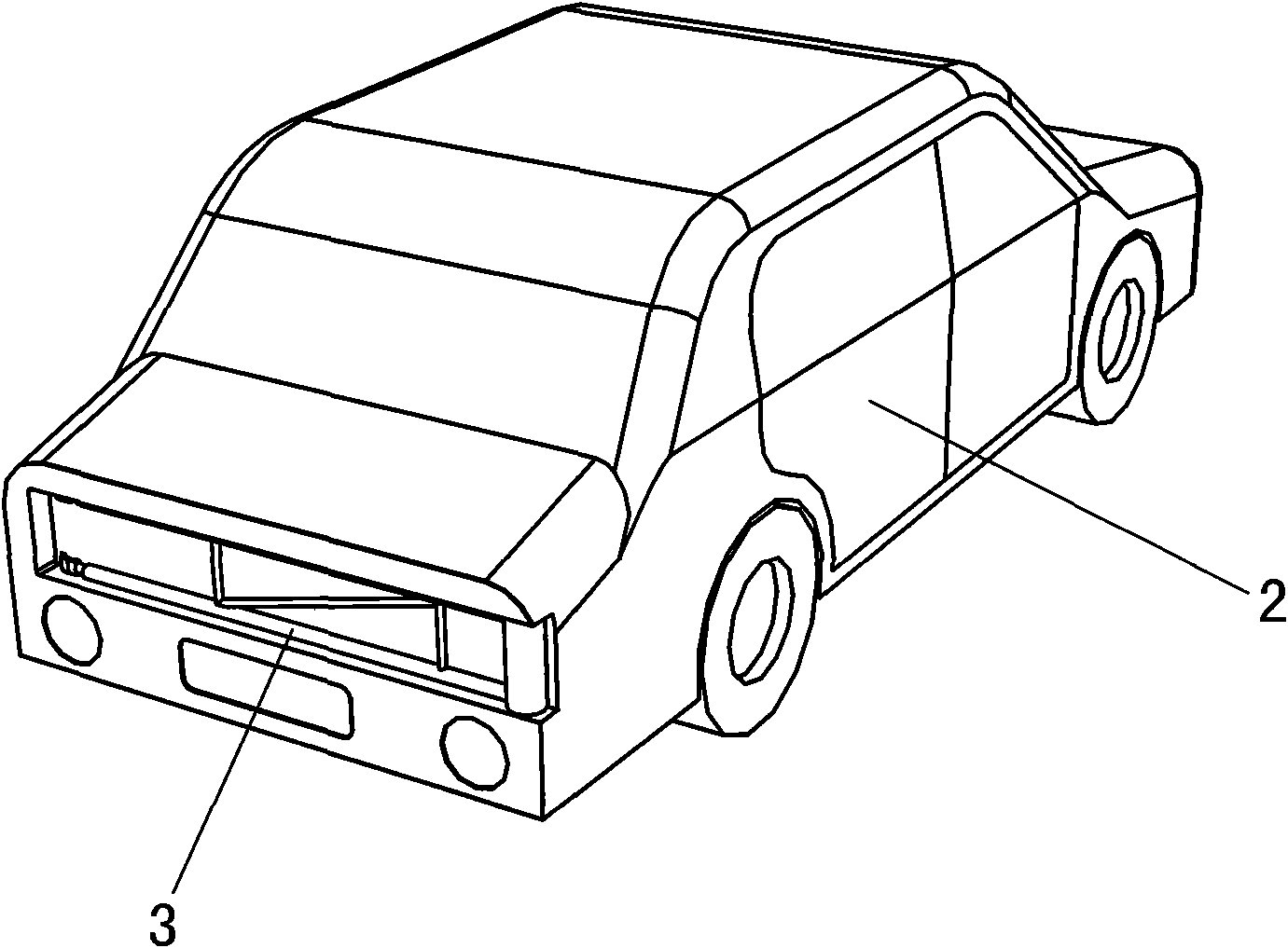
[0019] Electric vehicles described in the present invention include large-scale electric vehicles (such as electric buses, supercapacitor buses, buses), medium-sized electric vehicles (such as medium-sized buses), small electric vehicles (such as taxis, private cars, commercial vehicles, etc. ) and other types of electric vehicles, which can be pure electric vehicles or hybrid electric vehicles; they can be electric vehicles driven by batteries (such as lead-acid batteries, nickel-metal hydride batteries, lithium-ion batteries, lithium iron phosphate batteries, etc.) A car can also be an electric car that uses supercapacitors (or supercapacitor banks) to provide electric power.

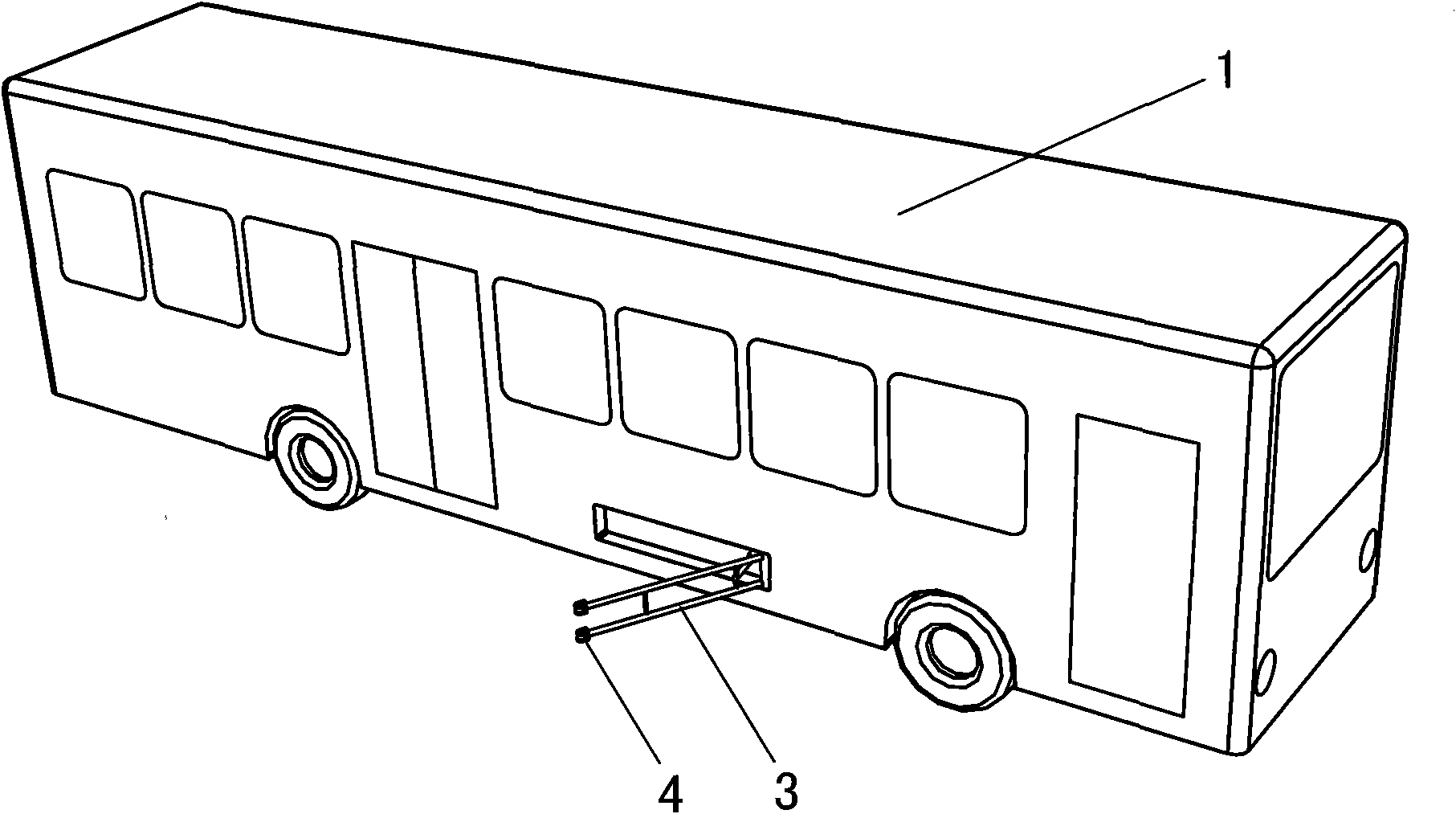
[0020] refer to figure 1 Embodiment, on the large-scale electric vehicle [1] described in the present invention, the motor that drives the vehicle and the on-board power supply that provides electric power for the motor are installed, and a collector pole [3] is also installed on the side of the vehic...


PUM


Abstract

The invention discloses an electric vehicle and a charging method thereof and relates to the technical field of energy-saving and environmentally-friendly electric vehicles. A current-collecting pole is arranged on the side face or the back face or the front face or the back part or the front part of the electric vehicle body. The vertical height of the current-collecting pole from the road surface is 20 to 150cm. Current-collecting heads are arranged at the outer end of the current-collecting pole. The number of the current-collecting heads is two. One current-collecting head is arranged on the other current-collecting end. A cable and a pushing mechanism are also arranged on the current-collecting pole. The charging method comprises the following steps that: when the electric vehicle needs to be charged, the current-collecting pole is extended towards the side of the vehicle body; and after the current-collecting heads are lapped to a charging power supply contact wire arranged on a power supply circuit on the side of a lane, the electrical power of an external power supply charges a vehicle-carried power supply. The electric vehicle can be charged while driven; and after the power supply circuit is reasonably arranged in a road network, the electric vehicle can be charged without stopping and is driven for a long time. The electric vehicle plays a great role in the promotion and the popularization of pure electric vehicles.

Description

technical field [0001] The invention relates to an electric vehicle, especially an electric vehicle capable of being charged while driving and a charging method thereof. Background technique [0002] Existing electric vehicles include trolleybuses that rely on grid power supply, and pure electric vehicles, hybrid electric vehicles, etc. that rely on vehicle power supply (battery or supercapacitor on board) to provide electric power. There are pantographs (or collector poles) on the roof of traditional trams and trolleybuses, and they rely on the catenary nets erected above the road to provide power for driving. The layout is difficult, and the catenary net erected above the road will also become a kind of visual pollution, and the mobility of the tram is poor, so it can only travel along the line with the catenary net erected, and the trams behind cannot overtake the trams in front. In order to solve the above-mentioned shortcomings of traditional trams, the Chinese Patent ...

Claims


Application Information

Patent Timeline
IPC IPC(8): B60L5/42
Inventor 周良勇
Owner 周良勇
Why Eureka
Try Eureka