Oil cylinder of static pressure vibration exciter

A technology of exciter and oil cylinder, which is applied in the direction of fluid pressure actuating device, fluid pressure actuating system components, mechanical equipment, etc., can solve the problem of the increase of external leakage of the hydraulic system, the decrease of the lateral force resistance of the piston rod, and the poor test repeatability. and other problems, to achieve the effect of low power consumption, good accuracy retention and compact structure

Inactive Publication Date: 2011-05-04
ZHEJIANG UNIV
View PDF6 Cites 10 Cited by
  • Summary
  • Abstract
  • Description
  • Claims
  • Application Information

AI Technical Summary

Problems solved by technology

[0002] Ordinary servo exciter cylinders are widely used in hydraulic vibration tables. For ultra-high-frequency high-thrust hydraulic vibration tables, the piston and piston rod of the exciter cylinder perform high-speed reciprocating motion together, and at the same time, they must bear large lateral forces. The friction between the piston, the piston rod and the cylinder wall and the seal intensifies, and the external leakage of the hydraulic system increases, so the repeatability of the test is poor.
Chinese patent CN11877140A discloses a hydrostatic support-guided hydraulic cylinder, which has four rectangular oil chambers on the inner wall of the hydrostatic bearing and four oil return grooves along the axial direction, so that after the oil enters the oil chamber, it will The oil returns alo

Method used


Image

  • Oil cylinder of static pressure vibration exciter
  • Oil cylinder of static pressure vibration exciter
  • Oil cylinder of static pressure vibration exciter

Examples


Example Embodiment

[0016] The present invention will be described in detail below in conjunction with the drawings.

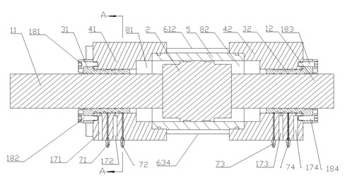
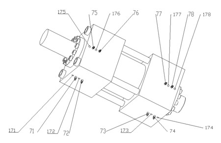
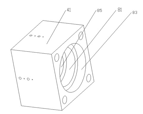
[0017] Such as Figure 1 to Figure 7 As shown, the cylinder of the static pressure exciter of the present invention includes a cylinder tube 5 and a piston 2 placed in the inner cavity of the cylinder tube. Two seals are used between the cylinder barrel 5 and the piston 2, which can significantly improve the sealing effect. Both ends of the piston 2 are fixedly connected to a piston rod 11 and a piston rod 12. The piston rod 11 and the piston rod 12 are respectively fixedly connected with the piston 2 in a threaded manner. The piston rod 11 and the piston rod 12 respectively extend out of the cylinder 5 Cavity. The hydrostatic bearing 31 is fixedly connected to the end cover 41 by bolts 181 and 182; the hydrostatic bearing 32 is fixedly connected to the end cover 42 by bolts 183 and 184. Such as Figure 5 As shown, the cross-sections of the hydrostatic bearing 31 and the hydrostat...


PUM


Abstract

The invention discloses an oil cylinder of a static pressure vibration exciter, which is characterized in that the two ends of a piston are respectively fixedly connected with a piston rod, and each piston rod stretch out of an inner cavity of a cylinder barrel; the transverse section of a static-pressure bearing is in the shape of a circular ring, the outer wall of each static-pressure bearing is axially provided with annular external oil grooves at certain intervals, the inner wall of the static-pressure bearing is axially provided with annular internal oil grooves, and each annular external oil groove is correspondingly communicated with an annular external oil groove by a first through hole; an end cover is axially provided with a second through hole; the piston rods respectively correspondingly pass through a static pressure bearing, and the static pressure bearings are respectively fixedly connected with an end cover, the two ends of the cylinder barrel are respectively arrangedin a big hole of the second through hole of a corresponding end cover, and the two end covers are fixedly connected by lock bolts; and the shell of each end cover is provided with an oil inlet and a corresponding oil outlet, one of two adjacent annular external oil grooves is communicated with the corresponding oil inlet, and the other annular external oil groove is communicated with the corresponding oil outlet. The oil cylinder disclosed by the invention can resist large lateral forces, and reduce the friction between the piston and the static-pressure bearings.

Description

technical field [0001] The invention relates to a static pressure vibration exciter oil cylinder , It can be widely used in the fields of single-degree-of-freedom and multi-degree-of-freedom hydraulic vibration tables, and also has related applications in some aerospace products and metallurgical industries. Background technique [0002] Ordinary servo exciter cylinders are widely used in hydraulic vibration tables. For ultra-high-frequency high-thrust hydraulic vibration tables, the piston and piston rod of the exciter cylinder perform high-speed reciprocating motion together, and at the same time, they must bear large lateral forces. The force makes the friction between the piston, piston rod and the cylinder wall and seal intensifies, and the external leakage of the hydraulic system increases, so the repeatability of the test is poor. Chinese patent CN11877140A discloses a hydrostatic support-guided hydraulic cylinder, which has four rectangular oil chambers on the inner...

Claims


Application Information

Patent Timeline
IPC IPC(8): F15B21/12
Inventor 陈章位文祥
Owner ZHEJIANG UNIV
Why Eureka
Try Eureka