Sound surface wave measuring sensor and parameter analytical method

A technology for measuring sensors and surface acoustic waves, which is used in measuring devices, measuring heat, and transmitting sensing components using wave/particle radiation devices. and other problems, to achieve the effect of ensuring large-scale and high-precision, simple structure, and solving large-scale accurate detection of physical quantities

Inactive Publication Date: 2011-05-04
李天利 +1
View PDF3 Cites 26 Cited by
  • Summary
  • Abstract
  • Description
  • Claims
  • Application Information

AI Technical Summary

Problems solved by technology

In the existing scheme, the structure of the surface acoustic wave sensor is simple, but due to the characteristics of surface acoustic wave transmission, the measurement range and accuracy of the physical quantity measured by the sensor cannot be guaranteed at the same time, that is, if the surface acoustic wave sensor has a large measurement range , the measurement accuracy is relatively low; if the surface acoustic wave sensor has high measurement accuracy, the measurement range will not be very large. It is difficult to find a large measurement range in the existing surface acoustic wave sensor while ensuring high Accurate Surface Acoustic Wave Sensors
In another existing solution, due to the structure of the surface acoustic wave sensor itself, only one radio frequency pulse query signal is sent to the sensor in each sensor measurement cycle, so the amount of information obtained from the sensor is small, and it is impossible to achieve large-scale high-resolution Measurement of Accuracy

Method used


Image

  • Sound surface wave measuring sensor and parameter analytical method
  • Sound surface wave measuring sensor and parameter analytical method
  • Sound surface wave measuring sensor and parameter analytical method

Examples


Embodiment Construction

[0025] The present invention will be further described below in conjunction with the accompanying drawings and embodiments.

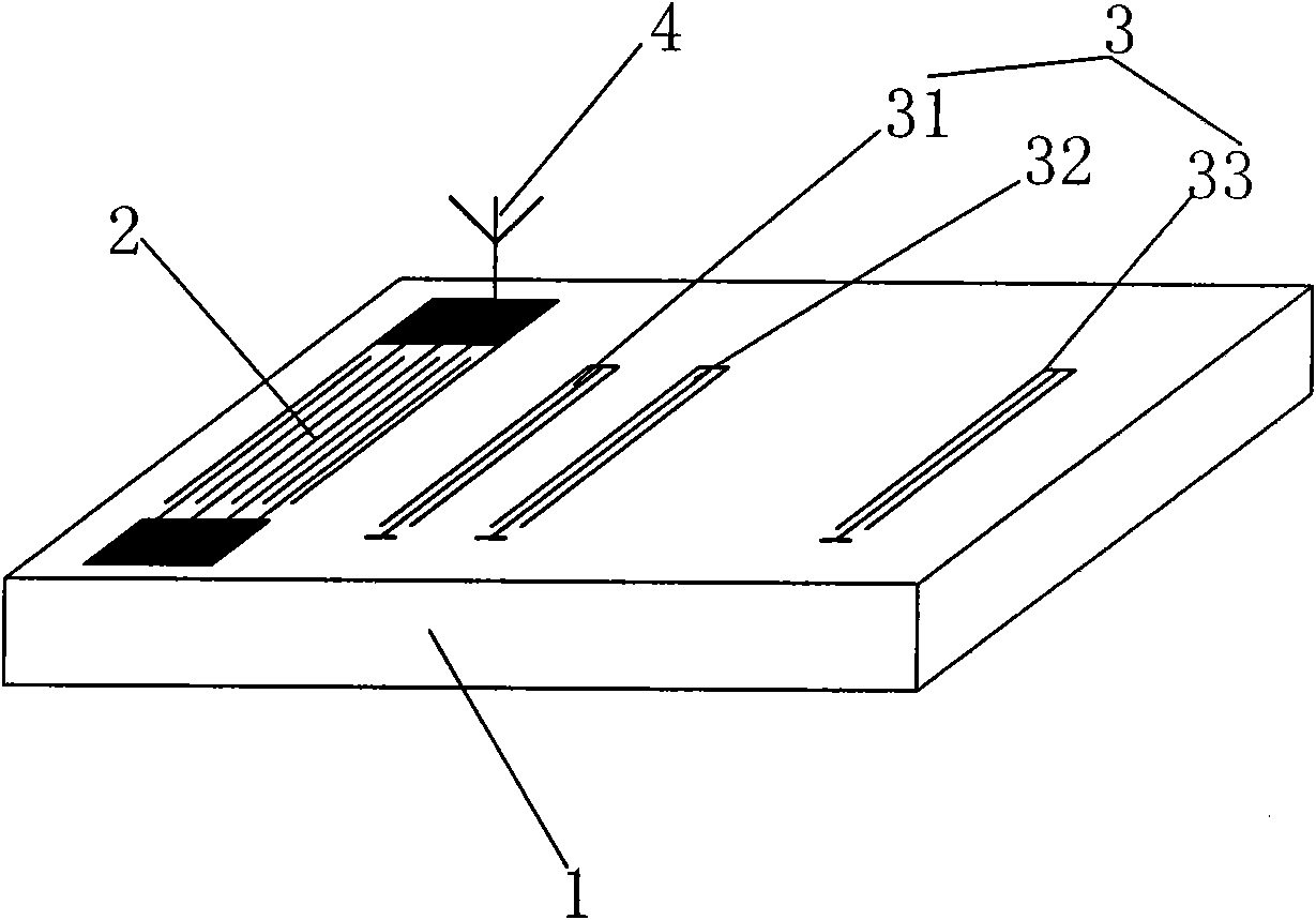
[0026] Such as figure 1 As shown, the present invention discloses a surface acoustic wave measurement sensor, which includes: a piezoelectric substrate 1, an interdigital transducer 2, a reflector 3 and an antenna 4, wherein;

[0027] Piezoelectric substrate 1, which is the sensing mechanism of the physical quantity to be measured, its thickness can be different according to the type and range of the physical quantity to be detected (such as the size of pressure, the range of temperature), by selecting different thicknesses to be processed during design Wafers are adjusted accordingly. The piezoelectric substrate 1 is made of a wafer material with piezoelectric properties. In this embodiment, the wafer material is a lithium niobate piezoelectric crystal slice in the Y-cut Z direction.

[0028] The interdigital transducer 2 and the reflector 3 are depo...


PUM


Abstract

The invention relates to a sound surface wave measuring sensor and a parameter analytical method. The sensor comprises a piezoelectric base, an interdigital transducer and a reflector, wherein the piezoelectric base is used for inducting physical quantity to be measured; the interdigital transducer and the reflector are deposited on the upper surface of the piezoelectric base through a surface micromachining process; the interdigital transducer is used for receiving drive energy required by the operation of the sound surface wave measuring sensor through an antenna connected with the interdigital transducer and returning a radio frequency pulse echo signal through the antenna; and the reflector is used for generating the radio frequency pulse echo signal. Compared with the prior art, the invention has the following technical characteristics: the physical quantity can be detected with high precision in a wide range on the premise of ensuring certain signal intensity; the problem that the sound surface wave sensor in the prior art can only meet one index in the range and the precision of signal measurement and the range and the precision of signal measurement cannot be met simultaneously is solved; the sound surface wave measuring sensor has simple structure; and by using a certain parameter analytical method, the measured physical quantity generates a corresponding feedback signal and the problem that the physical quantity can be accurately detected by the sensor in a wide range can be solved.

Description

technical field [0001] The invention belongs to the technical field of surface acoustic wave sensing, and specifically relates to a surface acoustic wave measurement sensor and a parameter analysis method. The sensor is a wireless passive surface acoustic wave physical parameter measurement sensor, which can simultaneously detect the external environment in a large range and with high precision. The change of the physical quantity to be measured, the analysis method specifically refers to the method of analyzing the parameters of the physical quantity feedback signal detected by the sensor by applying the surface acoustic wave delay line theory. Background technique [0002] Due to the simple structure, small size, light weight, good stability, wireless connection, no power drive and high sensitivity of the surface acoustic wave sensor, it can be used in a variety of complex and harsh environments. Since the 1980s, the United States, Germany, Japan and other countries have e...

Claims


Application Information

Patent Timeline
Patent Type & Authority Applications(China)
IPC IPC(8): G01D5/48G01K11/22
Inventor 李天利朱克敏
Owner 李天利
Why Eureka
Try Eureka