Miniature specimen creep test system and test method

A creep test and micro-sample technology, which is applied in the field of micro-sample creep test system to improve the overall accuracy, ensure the measurement accuracy, and facilitate processing and installation.

Inactive Publication Date: 2011-05-04
EAST CHINA UNIV OF SCI & TECH
View PDF4 Cites 47 Cited by
  • Summary
  • Abstract
  • Description
  • Claims
  • Application Information

AI Technical Summary

Problems solved by technology

[0013] At present, Krause, Chen, Dusza, and Lin et al. through bending creep tests, respectively, ceramics, MoSi 2 The creep properties of sialon and sialon materials are evaluated, but there are few bending creep...

Method used


Image

  • Miniature specimen creep test system and test method
  • Miniature specimen creep test system and test method
  • Miniature specimen creep test system and test method

Examples


Embodiment 1

[0051] Embodiment 1 micro sample creep test system

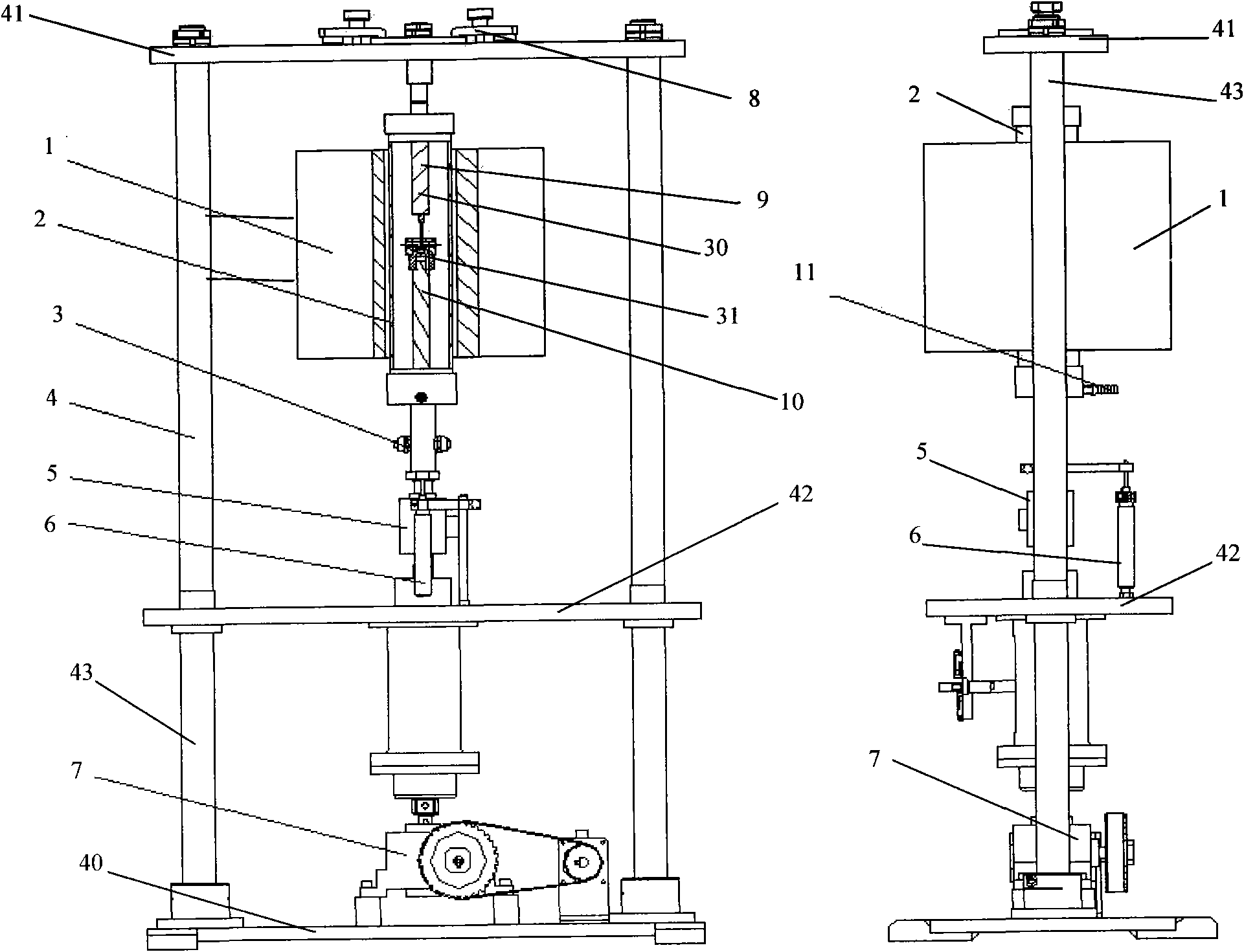
[0052] Such as figure 1 As shown, the micro-sample creep test system of the present invention includes a main frame 4, a high temperature furnace 1, a servo motor loading device 7, a distance measuring device, a force measuring device, a cooling system 3, a gas supply device (not shown), Clamping mechanism 30, quartz tube 2.

[0053] The main frame 4 is composed of a base 40 , an upper beam 41 , a middle beam 42 and two columns 43 .

[0054] The servo motor loading device 7 is placed under the middle beam 42 , and its lower end is fixed on the base 40 . The upper end passes through the middle beam 42 . The servo motor drives the reducer through the synchronous belt, the reducer drives the lead screw, and the lead screw nut drives the lower rod to move axially through the pull tube, which can be used for compression-compression fatigue tests. force device. In order to ensure the coaxiality of the upper and lower sides, the...

Embodiment 2

[0061] Embodiment 2 micro sample creep test system

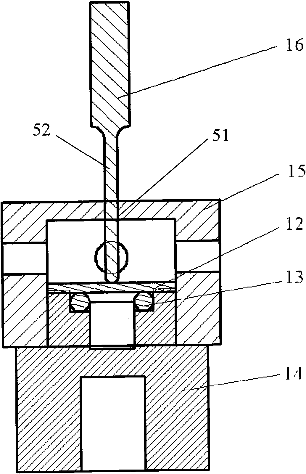
[0062] In this embodiment, the micro-sample creep test system is basically the same as that in Embodiment 1, the only difference is that the fixture set is a four-point bending fixture set, and the structure is as follows Figure 5 shown. The four-point bending fixture kit can realize the theoretical model of four-point bending with high precision and full contact with the ambient gas. The structure is basically the same as the three-point bending fixture kit, such as Figure 6 As shown, the difference is that the pressure rod and the positioning sleeve have two rectangular holes 51 in the middle of the four-point bending positioning sleeve 17, and the pressure rod 18 has two pressure heads 52.

Embodiment 3

[0063] Embodiment 3 micro sample creep test system

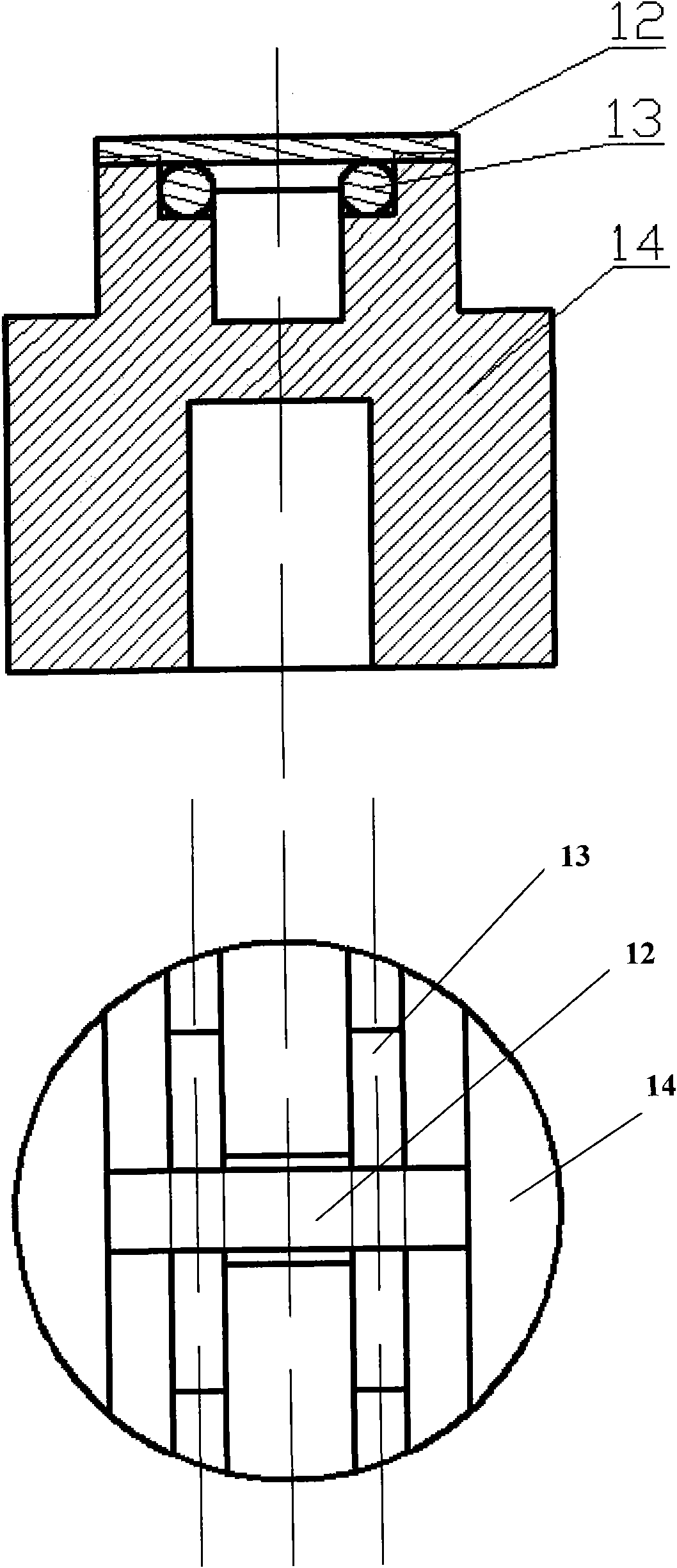
[0064] The micro-sample creep test system in this embodiment is basically the same as that in Embodiment 1, except that the fixture set is a small punching fixture set. Such as Figure 7 As shown, the feature of the small punching fixture kit is that the upper die 21 and the lower die 23 are threaded, and the small punching sample 22 is well fixed between the upper die 21 and the lower die 23, and on the side of the lower die 23 There are small holes, so that the lower surface of the sample 22 can fully contact with the ambient gas, which is convenient for studying the influence of environment and creep coupling.

[0065] Small punching lower die 23 is circular, and there is a shallow circular concave hole in the middle, which is used to place small punching sample 22, and the other end has internal thread, which can be connected with lower support rod 10. There are small holes on the side of the lower mold 23, so that the...


PUM


Abstract

The invention discloses a miniature specimen creep test system and a miniature specimen creep test method which can control a test environment. The system comprises a host frame, a high-temperature furnace, a servo motor loading device, a distance measuring device, a force measuring device, a cooling system, a clamping mechanism, a quartz tube and an air supply device, wherein the servo motor loading device is arranged at the bottom of the host frame; the force measuring device is connected with the servo motor loading device and is arranged above the servo motor loading device; a sensing head of the distance measuring device is sleeved between a force sensor and the cooling system; the cooling system is arranged above the force sensor; the clamping mechanism is arranged above the cooling system and passes through the quartz tube; the upper end of the clamping mechanism is fixed at the upper end of the host frame; the high-temperature furnace is sleeved out of the quartz tube; and the air supply device can convey air into the space formed by the clamping mechanism and the quartz tube through an air inlet tube. In the system and the method, fewer materials are taken; three-point bending, four-point bending and a small-punch creep test can be performed in various gaseous environments; the high-temperature mechanical property of a material under actual working conditions can be met; and the overall precision is high.

Description

technical field [0001] The invention relates to a micro-sample creep test system and a test method. Background technique [0002] In industries with high energy consumption such as thermal power, nuclear power and petrochemical, it is necessary to increase technical parameters such as temperature and pressure to improve the utilization rate of resources and achieve the goal of energy saving and emission reduction. Higher requirements are put forward for related equipment. How to ensure the safe and stable operation of equipment in high temperature and harsh environments has become a major research topic. In a high-temperature environment, the main form of failure is creep, and it is necessary to fully understand the creep performance of in-service equipment for life assessment. [0003] At present, the material performance evaluation of in-service equipment is mainly based on non-destructive testing and micro-sample testing. However, the current non-destructive testing te...

Claims


Application Information

Patent Timeline
IPC IPC(8): G01N3/28G01N3/04
Inventor 轩福贞郎欣王正东涂善东
Owner EAST CHINA UNIV OF SCI & TECH
Why Eureka
Try Eureka