Loop bandwidth control device and method of phase locked loop

A technology of a control device and a phase-locked loop, which is applied in the direction of automatic power control, electrical components, etc., can solve the problems of long locking time and the inability of the loop filter 14 to effectively suppress noise, and achieve the effect of shortening the time.

Active Publication Date: 2013-04-24
MEDIATEK INC
View PDF0 Cites 0 Cited by
  • Summary
  • Abstract
  • Description
  • Claims
  • Application Information

AI Technical Summary

Problems solved by technology

[0006] When the loop bandwidth of the loop filter 14 is small, although the loop filter 14 can effectively filter out the noise caused by the switching of the input reference frequency and the charge pump 12 and reduce the non-ideal effect caused by the jitter, but due to The length of the locking time is inversely proportional to the size of the loop bandwidth, so its disadvantage is that the locking time is too long
Conversely, if the loop bandwidth of the loop filter 14 is increased, although the locking time can be shortened, it may also cause the loop filter 14 to be unable to effectively suppress noise.

Method used


Image

  • Loop bandwidth control device and method of phase locked loop
  • Loop bandwidth control device and method of phase locked loop
  • Loop bandwidth control device and method of phase locked loop

Examples


Embodiment Construction

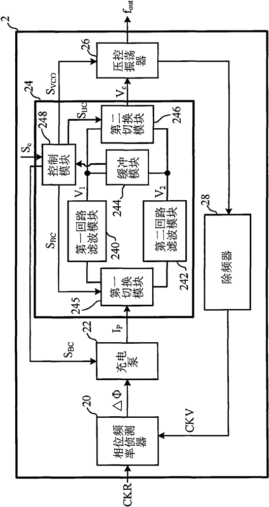
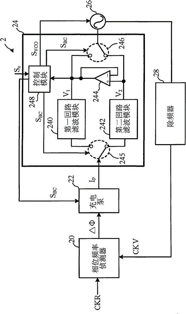
[0039] The first specific embodiment according to the present invention is a phase-locked loop. Please refer to figure 2, figure 2 is the functional block diagram of the phase-locked loop. Such as figure 2 As shown, the PLL 2 mainly includes a phase frequency detector 20 , a charge pump 22 , a loop bandwidth control device 24 , a voltage controlled oscillator 26 and a frequency divider 28 . The loop bandwidth control device 24 includes a first loop filter module 240 , a second loop filter module 242 , a buffer module 244 , a first switch module 245 , a second switch module 246 and a control module 248 .

[0040] Wherein, the phase frequency detector 20 is coupled to the charge pump 22; the first switching module 245 is coupled to the input terminals of the first loop filter module 240 and the second loop filter module 242 and the charge pump 22; the buffer module 244 is Coupled to the output terminals of the first loop filter module 240 and the second loop filter module...


PUM


Abstract

The invention discloses loop bandwidth control device and method of a phase locked loop, which can greatly shorten the time required for controlling the voltage of a correction voltage-controlled oscillator. The loop bandwidth control device comprises a first loop filtering module, a second loop filtering module, a control module, a first switching module and a second switching module, wherein the first loop filtering module and the second loop filtering module respectively output a first voltage and a second voltage; the bandwidth of the second loop filtering module is different from the bandwidth of the first loop filtering module; the control module generates a bandwidth control signal according to the first voltage or the second voltage; the first switching module ensures that a charge pump and the first loop filtering module or the second loop filtering module form a passage according to a bandwidth control signal; and the second switching module ensures that the voltage-controlled oscillator and the first loop filtering module or the second loop filtering module form a passage according to the bandwidth control signal.

Description

technical field [0001] The present invention relates to a phase-locked loop, in particular, to a loop bandwidth control device and a loop bandwidth control method applied to a phase-locked loop. Background technique [0002] Generally speaking, a phase locked loop (Phase Locked Loop, PLL) can be regarded as a feedback circuit system of an output phase and an input phase, which is used to input a low-frequency periodic signal and output a high-frequency periodic signal, and There is some constant phase relationship between the input and the output. The phase-locked loop mainly includes a phase-frequency detector, a charge pump, a loop filter and a voltage-controlled oscillator. In fact, phase-locked loops have been widely used in the fields of electronics and communications, such as memory, microprocessors, hard disk drives, radio frequency wireless transceivers, and optical fiber transceivers. [0003] Please refer to figure 1 , figure 1 A functional block diagram of a t...

Claims


Application Information

Patent Timeline
Patent Type & Authority Patents(China)
IPC IPC(8): H03L7/08
Inventor 颜仕杰王耀祺谢明谕
Owner MEDIATEK INC
Why Eureka
Try Eureka