
Enclosed compressor and refrigeration cycle device

A compressor, hermetically sealed technology, applied to parts of pumping devices for elastic fluids, mechanical equipment, engine components, etc., can solve problems such as wear, failure to improve bearing reliability, etc.

Inactive Publication Date: 2011-05-04
TOSHIBA CARRIER CORP
View PDF5 Cites 25 Cited by
  • Summary
  • Abstract
  • Description
  • Claims
  • Application Information

AI Technical Summary

Problems solved by technology

Therefore, localized wear occurs, and the reliability of the bearing cannot be sufficiently improved.

Method used


Image

  • Enclosed compressor and refrigeration cycle device
  • Enclosed compressor and refrigeration cycle device
  • Enclosed compressor and refrigeration cycle device

Examples


Embodiment Construction

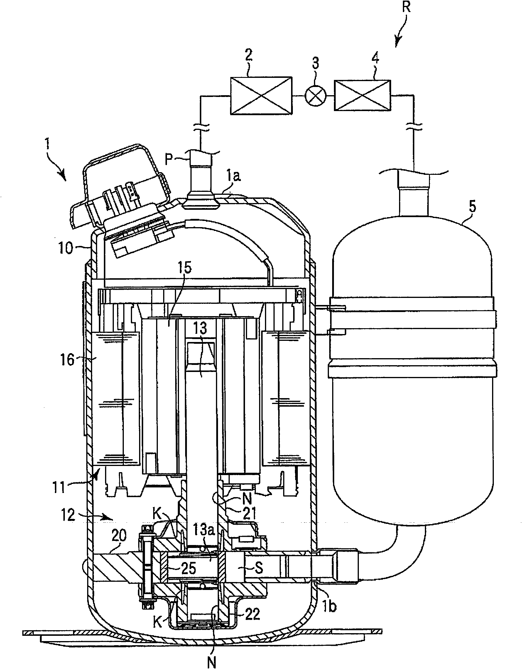
[0024] Embodiments of the present invention will be described below with reference to the drawings. figure 1 It is a longitudinal sectional view of the hermetic compressor 1 and a configuration diagram of the refrigeration cycle of the refrigeration cycle apparatus R.

[0025] 1 in the figure is a hermetic rotary compressor (hereinafter simply referred to as "compressor"), and the compressor 1 will be described below. A refrigerant pipe P is connected to the upper end of the compressor 1 , and a condenser 2 , an expansion valve (expansion device) 3 , an evaporator 4 , and an accumulator 5 are sequentially provided on the refrigerant pipe P. Further, a refrigerant pipe P is connected from the accumulator 5 to a side portion of the compressor 1, and the refrigeration cycle of the refrigeration cycle apparatus R is constituted by these members.

[0026] Next, the compressor 1 will be described. The compressor 1 includes an airtight container 10 , and a motor unit 11 is housed i...


PUM


Abstract

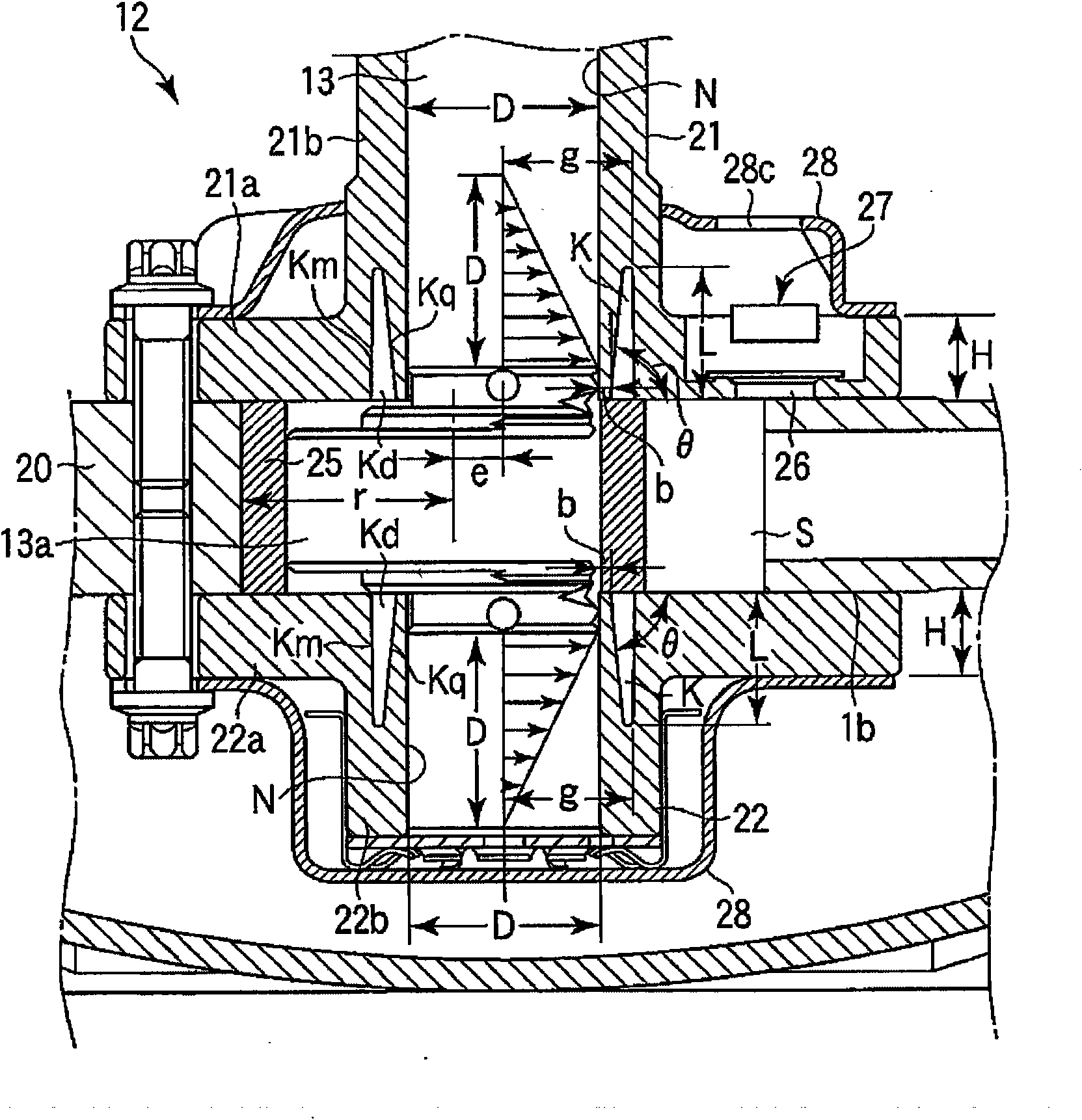
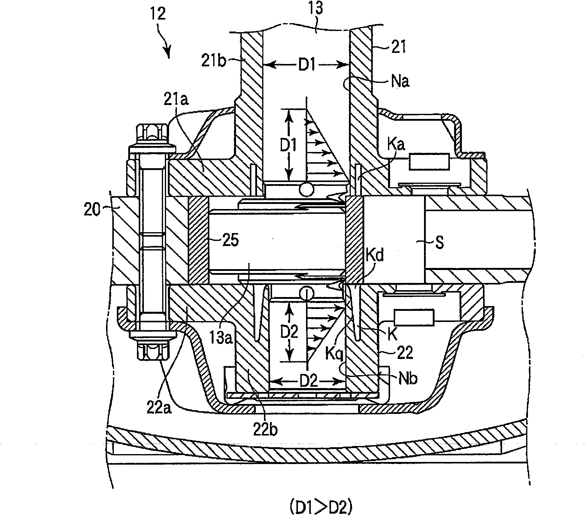
In the enclosed compressor (1), a motor section (11) and a compression mechanism section (12) connected to the motor section through a rotating shaft (13) are contained in an enclosed container (10). The compression mechanism section is provided with a cylinder (20) having an inner diameter hole (S), and also with a main bearing (21) and a sub-bearing (22) which have a bearing hole (N) rotatably supporting the rotating shaft and which close the inner diameter hole in the cylinder to form therein a cylinder chamber. At least either the main bearing or the sub-bearing has an annular groove (K) open to the cylinder chamber side. The inner peripheral surface of the annular groove has a tapered shape having a diameter gradually increased from the cylinder chamber side toward the side opposite to the cylinder chamber. The depth (L) of the annular groove is set greater than or equal to 40% of the diameter (D) of the bearing hole. Even if flexural deformation occurs in the rotating shaft due to a compression load in the cylinder, at least either the main bearing or sub-bearing is prevented from making partial contact with the rotating shaft, and this enhances the reliability of the compressor and extends the life of the compressor. The invention also provides a refrigeration cycle device which is equipped with the enclosed compressor to constitute the refrigeration cycle, thus enhancing the refrigeration efficiency.

Description

technical field [0001] The present invention relates to a hermetic compressor in which a bearing structure is improved, and a refrigeration cycle device in which the hermetic compressor is provided to constitute a refrigeration cycle (refrigeration cycle). Background technique [0002] In refrigeration cycle apparatuses, a rotary hermetic compressor is often used, in which a motor unit is housed in a hermetic container and connected via a rotating shaft (crank shaft). In the compression mechanism part of the motor part. In such a compressor, a refrigerant is introduced into a compression chamber formed in a cylinder and compressed, whereby a compression load acts on a rotary shaft. [0003] Therefore, the rotating shaft is bent and deformed, and if no measures are taken, the rotating shaft portion in the bending direction and the bearing that pivotally supports the rotating shaft will partially come into contact. The smooth rotation of the rotating shaft will be affected, ...

Claims


Application Information

Patent Timeline
Patent Type & Authority Applications(China)
IPC IPC(8): F04C29/00F04C18/356
CPCF01C21/02F04C18/3562F04C23/001F04C23/008F04C29/12F04C2240/52F04C2240/601
Inventor 三浦一彦里馆康治二见俊彦
Owner TOSHIBA CARRIER CORP
Learn More