Grinding tools and grinding devices
A technology of grinding tool and grinding sheet, which is applied in the direction of grinding tools, etc., can solve the problems of grinding processing and failure to realize practicality, and achieve the effects of reducing detachment, no scratches on the quality of the processed surface, and suppressing local contact
- Summary
- Abstract
- Description
- Claims
- Application Information
AI Technical Summary
Problems solved by technology
Method used
Image
Examples
Embodiment 1
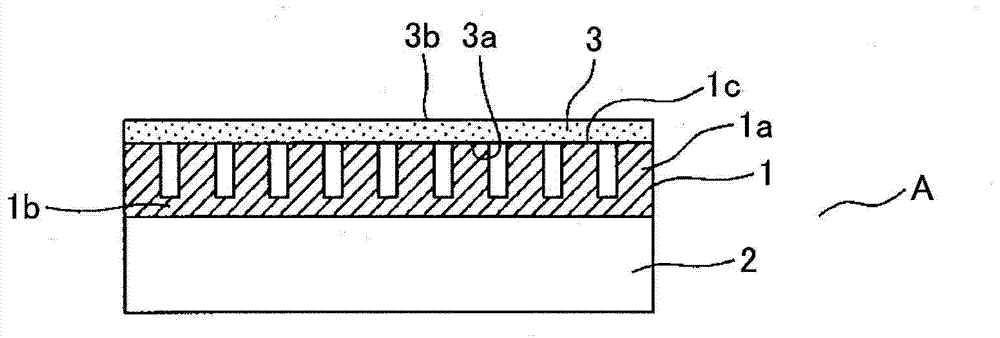
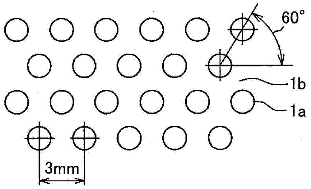
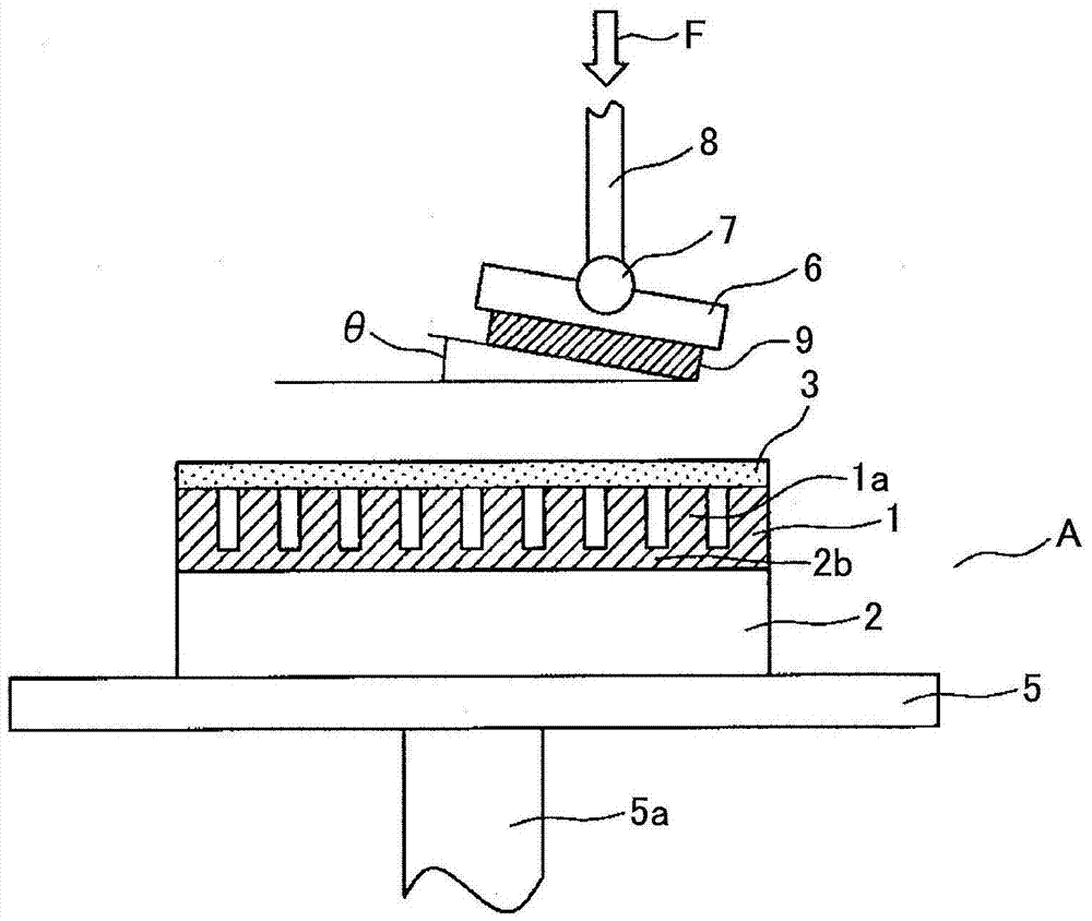
[0082] First, a second elastic layer was made. As a material of the elastomer, natural rubber (asker C hardness: 85) was used. The thickness of the part of the flat part 1b constituting the second elastic layer is 0.35 mm, and a plurality of (many) cylindrical protrusions 1a are formed integrally with the flat part 1b. The diameter of the convex portion 1a is 2mm, such as figure 2 As shown, they are arranged in a staggered manner at 60°, the interaxial distance (horizontal interval) between each other is 3mm, and the height is 1mm. When producing this second elastic layer, natural rubber is poured into a stainless steel mold satisfying the above-mentioned dimensions, and after molding, it is released from the mold to integrally mold the flat portion 1b and the plurality of protrusions. Regarding the softness of the second elastic layer obtained in this way, the value measured based on the ASKER C hardness measurement of the second elastic layer was 73.
[0083] As the firs...
Embodiment 2
[0098] Then, the influence of the height of the convex portion of the second elastic layer was investigated. In the same manner as in Example 1 (thickness of the flat plate portion was fixed at 0.35 mm), an examination was conducted in which only the height of the cylinder of the convex portion was changed.
[0099] Figure 8 In , the horizontal axis is the ratio of the height of the convex portion / the thickness of the flat plate portion, and the vertical axis is the value measured based on the Asker C hardness measurement, showing the results of the investigation.
[0100] Regarding natural rubber (asker C hardness: 85), it can be understood that the rubber hardness decreases as the height of the convex portion becomes higher. Figure 9 (a) shows the detection status of the prescaler part when the ratio of the height of the convex part to the thickness of the flat part is 0.88. It can be understood here that when the ratio of the height of the convex part to the thickness o...
Embodiment 3
[0104] Similar to Example 1, however, instead of the predetermined portion, fixed on the surface of the composite elastic layer is a polishing film produced by fixing the abrasive grains disclosed in Patent Document 2 to the polishing surface using an adhesive. As a result of processing an optical glass disc (borosilicate glass (equivalent to BK7)) with a diameter of 100 mm adjusted to a maximum height roughness Rt of 2 μm, scratch-free and maximum height roughness Ry was obtained after 5 minutes of processing It is a mirror surface at 30nm. The polishing conditions at this time were: the number of plate rotations was 60 rpm, the processing pressure was 30 kPa, and the amount of pure water supplied as cooling water to the polishing surface was 200 ml / min. As a result of measuring the thickness of the polished material at 10 locations, the error was within 0.5 μm, and it was confirmed that the polishing was performed with sufficient high precision. Then, the grinding process w...
PUM
 Abstract
Description
Claims
Application Information
 - R&D
- Intellectual Property
- Life Sciences
- Materials
- Tech Scout
- Unparalleled Data Quality
- Higher Quality Content
- 60% Fewer Hallucinations
Browse by: Latest US Patents, China's latest patents, Technical Efficacy Thesaurus, Application Domain, Technology Topic, Popular Technical Reports.
© 2025 PatSnap. All rights reserved.Legal|Privacy policy|Modern Slavery Act Transparency Statement|Sitemap|About US| Contact US: help@patsnap.com


