Clutch release bearing

A technology for separating bearings and clutches, which is applied to clutches, bearings, mechanically driven clutches, etc., and can solve problems such as shortened bearing life

Active Publication Date: 2011-05-04
JTEKT CORP
View PDF3 Cites 6 Cited by
  • Summary
  • Abstract
  • Description
  • Claims
  • Application Information

AI Technical Summary

Problems solved by technology

[0003] When water invades into the inside of the clutch release bearing, lubricating oil such as grease sealed in the inside of the bearing deteriorates, and rust is formed inside the bearing, thus causing shortened bearing life

Method used


Image

  • Clutch release bearing
  • Clutch release bearing
  • Clutch release bearing

Examples


Embodiment 1

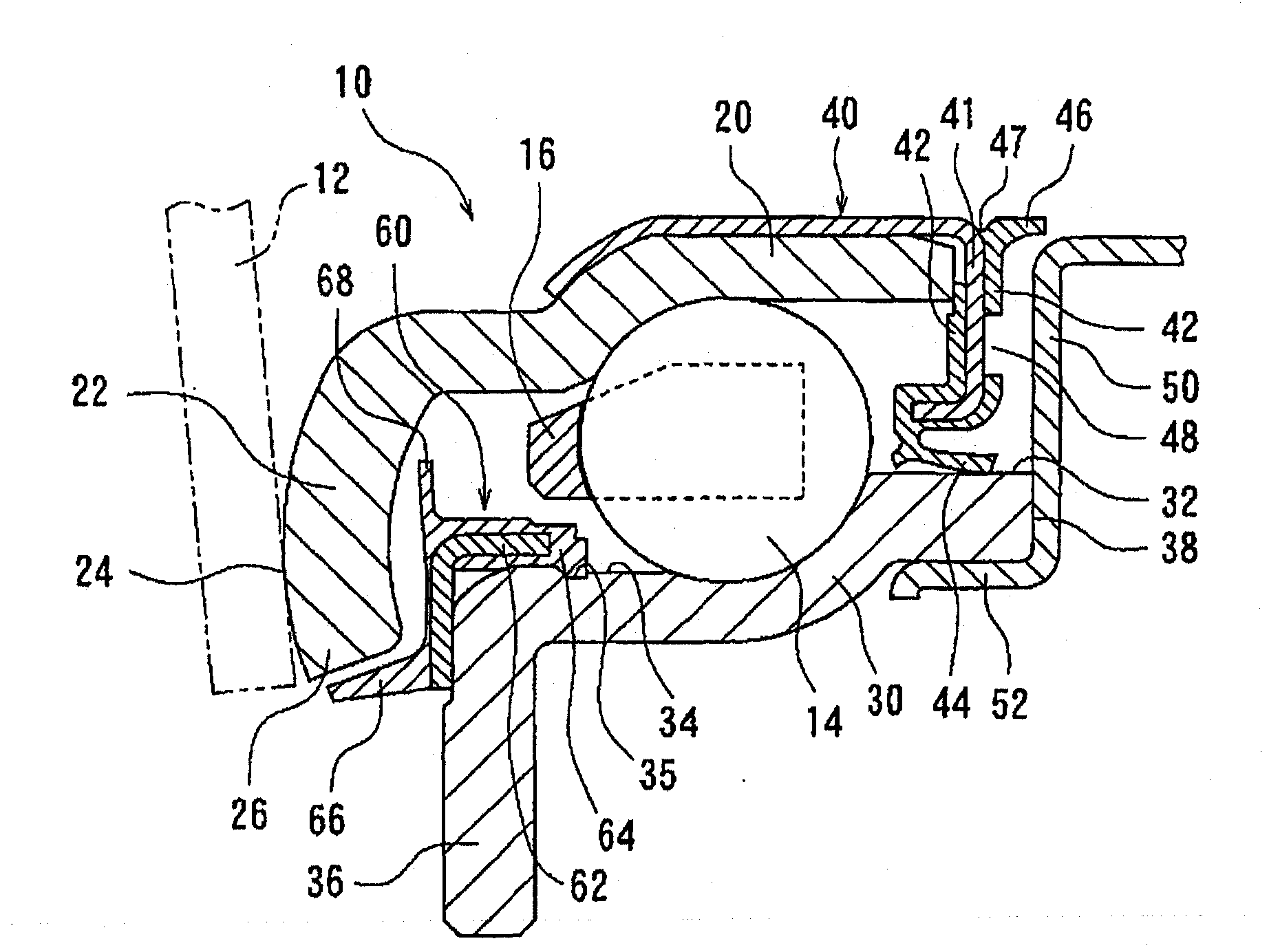
[0076] First, Embodiment 1 will be described. exist figure 1 A partial sectional view of the clutch release bearing 10 according to Embodiment 1 of the present invention is shown in . The clutch release bearing 10 is a clutch release bearing of the outer ring rotation type, and the clutch release bearing includes an outer ring 20, an inner ring 30, a plurality of balls (rolling elements) arranged between the outer ring 20 and the inner ring 30 in a rollable manner. ) 14 and a cage 16 that holds the ball 14 in a rotatable manner. An outer ring rib 22 extending radially inward is formed at one side end portion of the outer ring 20 , and an axially outer side of the outer ring rib 22 is also formed as a contact surface 24 that the diaphragm spring 12 is adapted to contact. The diaphragm spring 12 is a rotating part of the clutch mechanism of the present invention. Incidentally, the outer ring 20 and the inner ring 30 are formed by press working.

[0077] At the side axially ...

Embodiment 2

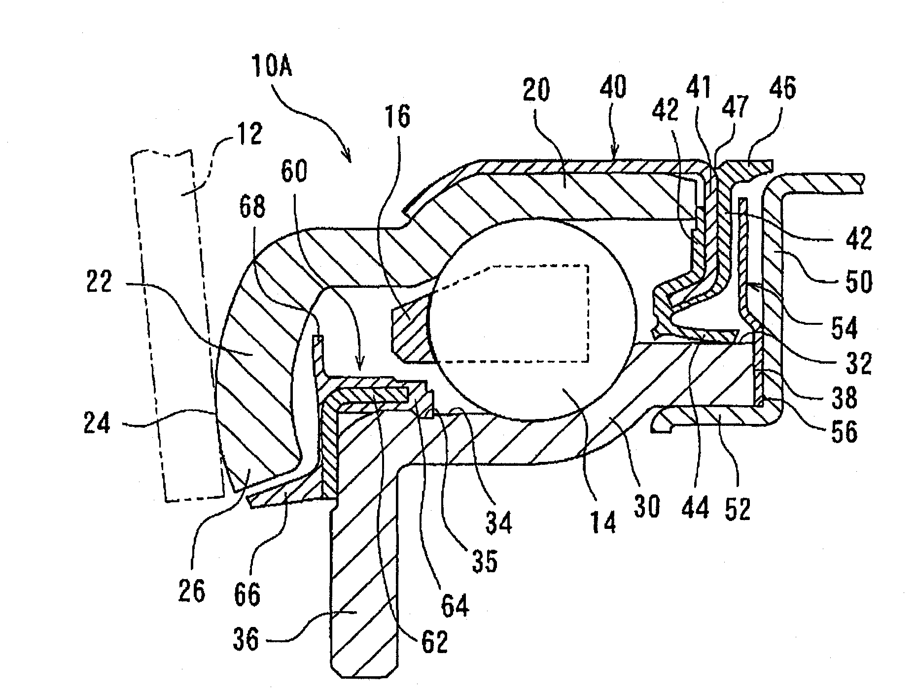
[0091] Next, Embodiment 2 will be described. exist image 3 A partial sectional view of a clutch release bearing 10A according to Embodiment 2 of the present invention is shown in . As compared with the clutch release bearing 10 of Embodiment 1, the clutch release bearing 10A is characterized in that a metal flinger 54 extending radially outward is provided between the first seal member 40 and the guide 50 , and the first The recess 48 is not formed in the bearing outer surface of the sealing member 40 .

[0092] The inner diameter portion 56 of the flinger 54 is externally fitted to the flange 52 of the guide 50, and in this state, the flange 52 of the guide 50 is press-fitted into the inner diameter surface of the inner ring 30, whereby the flinger The oil ring is integrated to the inner ring 30 and the guide 50 .

[0093] At the inner diameter side of the oil slinger 54 , said oil slinger 54 is held between the end 38 of the inner ring 30 and the bearing inner side of th...

Embodiment 3

[0103] Finally, Embodiment 3 will be described. exist Figure 4 A partial sectional view of the clutch release bearing 110 according to Embodiment 3 of the present invention is shown in . The clutch release bearing 110 is a clutch release bearing of the outer ring rotation type, and the clutch release bearing includes an outer ring 120, an inner ring 130, and a plurality of balls (rolling elements) arranged between the outer ring 120 and the inner ring 130 in a rollable manner. ) 114 and cage 116. An outer ring rib 122 extending radially inward is formed at one end of the outer ring 120 , and the bearing outer side of the outer ring rib 122 is also formed as a contact surface 124 that the diaphragm spring 112 is adapted to contact. The diaphragm spring 112 is a rotating component of the clutch mechanism of the present invention. Incidentally, the outer ring 120 and the inner ring 130 are formed by press working.

[0104] At the side axially opposite to the side where the o...


PUM


Abstract

Provided is a clutch release bearing whose water resistance is improved. A first sealing member (40) externally fitted to an outer ring (20) is disposed on the side opposite to the side, in an axis direction, on which an outer ring collar (22) of a clutch release bearing (10) is provided. A seal lip (44) that is in sliding contact with an outer-diameter surface (32) of an inner ring (30) is disposed at the end of the first sealing member (40) in an inner radial direction. A ring-shaped guide (50) is disposed on the bearing outer side of the first sealing member (40). An axial lip (46) that extends in the outward direction of the bearing to the radially outer side of the guide (50) is formed on the side face of the first sealing member (40) on the bearing outer side. The axial lip (46) andthe guide (50) are in non-contact close proximity and form a labyrinth. A groove (47) opening radially outward is formed at a joint portion of the axial lip (46) to the first sealing member (40).

Description

technical field [0001] The invention relates to a clutch release bearing. Specifically, the present invention relates to a seal structure of a clutch release bearing of the type in which an outer ring rotates in contact with a rotating member of a clutch mechanism. Background technique [0002] Clutch release bearings are incorporated in clutch units installed between the car engine and transmission. Regarding such clutch release bearings, there are outer ring rotating / inner ring fixed types in which the outer ring rotates in contact with a rotating member of the clutch mechanism, such as a diaphragm spring, and outer ring fixed types in which the inner ring rotates in contact with a rotating member of the clutch mechanism. / Inner ring rotation type. [0003] When water invades into the inside of the clutch release bearing, lubricating oil such as grease sealed in the inside of the bearing deteriorates, and rust is formed inside the bearing, thus causing shortened bearing ...

Claims


Application Information

Patent Timeline
Patent Type & Authority Applications(China)
IPC IPC(8): F16D23/14
CPCF16C19/163F16D23/14F16J15/3256F16J15/4476F16C2361/43F16C33/80F16J15/164F16D2300/08F16C33/7886F16C33/805
Inventor 铃木章之杦本孝河村基司山口高平井上哲朗中川義崇
Owner JTEKT CORP
Why Eureka
Try Eureka