Gas cupola for melting metal

A cupola and metal technology, applied in the field of gas-fired cupolas for metal melting, can solve problems such as a large amount of coke, and achieve the effect of reducing the amount of use and efficient melting

Inactive Publication Date: 2011-05-04
AISIN TAKAOKA CO LTD
View PDF7 Cites 5 Cited by
  • Summary
  • Abstract
  • Description
  • Claims
  • Application Information

AI Technical Summary

Problems solved by technology

Therefore, there is a limit in efficiently and rapidly melting the charge
In addition, a gas cupola that uses the heat of coke to melt the charge in addition to the combustion flame of the burner is used. Although coke can be used to improve the melting ability of the combustion flame, in addition to the fuel burned by the burner , also requires a large amount of coke

Method used


Image

  • Gas cupola for melting metal
  • Gas cupola for melting metal
  • Gas cupola for melting metal

Examples


Embodiment approach 1

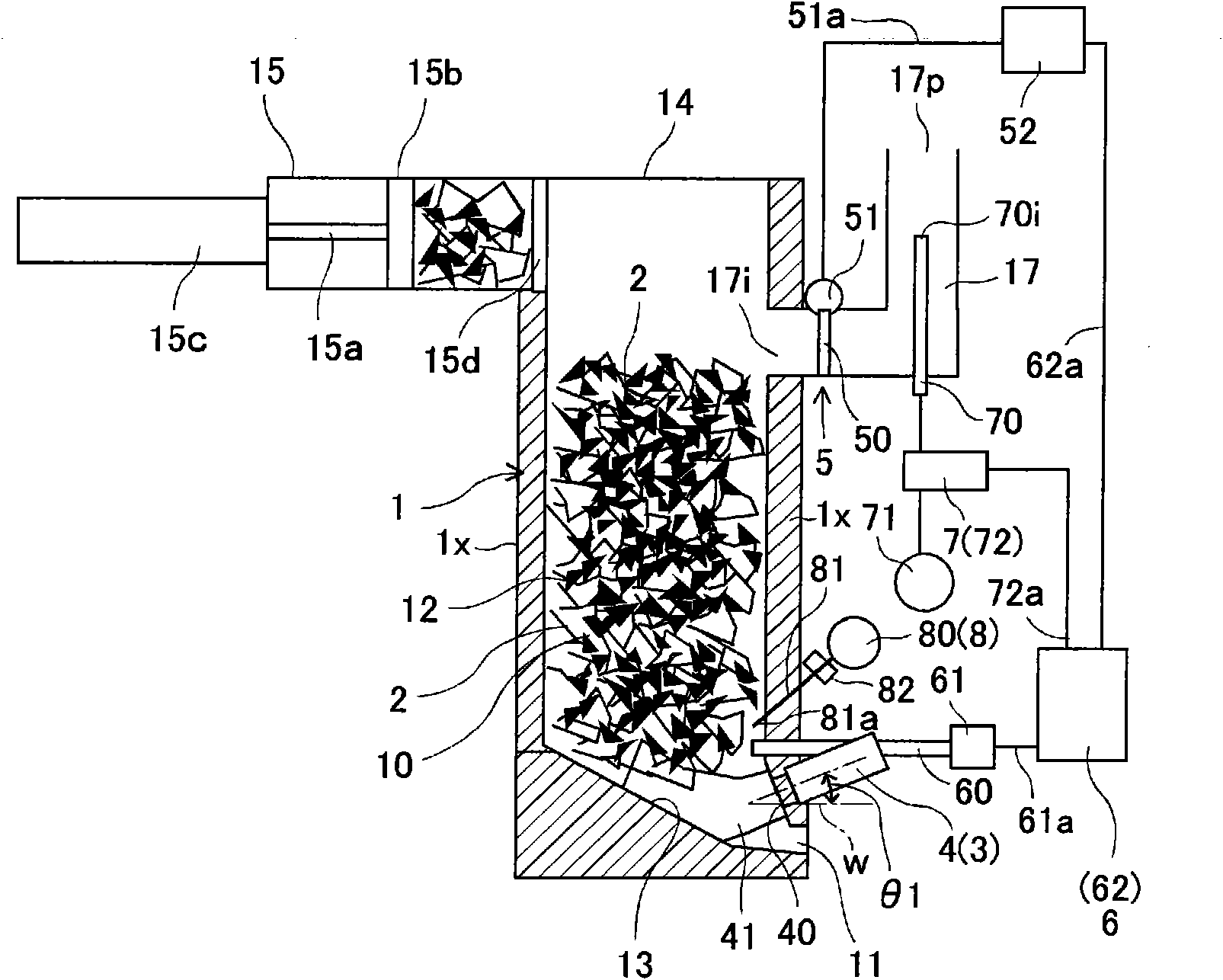
[0029] like figure 1 As shown, the gas-fired cupola for metal melting in this embodiment is used to form a cast iron melt, and includes a cylindrical furnace body 1 and a burner group 3 installed in the furnace body 1 . Examples of cast iron include flaky graphite cast iron, nodular graphite cast iron, and vermicular graphite cast iron. The body of furnace 1 is a vertical device along the direction of gravity. The body of furnace 1 is provided with a melting chamber 10 and a melt outlet 11. The melting chamber 10 is used to melt the charge 2 with metal as the base material. 11 is used to discharge the melt formed after the charge 2 is melted in the melting chamber 10 . A portion on the upper side in the melting chamber 10 is formed as a preheating belt 12 for preheating the charge 2 . A melt discharge port 11 is formed near the bottom of the furnace body 1 . On the bottom side of the melting chamber 10 , a hearth surface 13 that slopes down toward the melt outlet 11 side is...

Embodiment approach 2

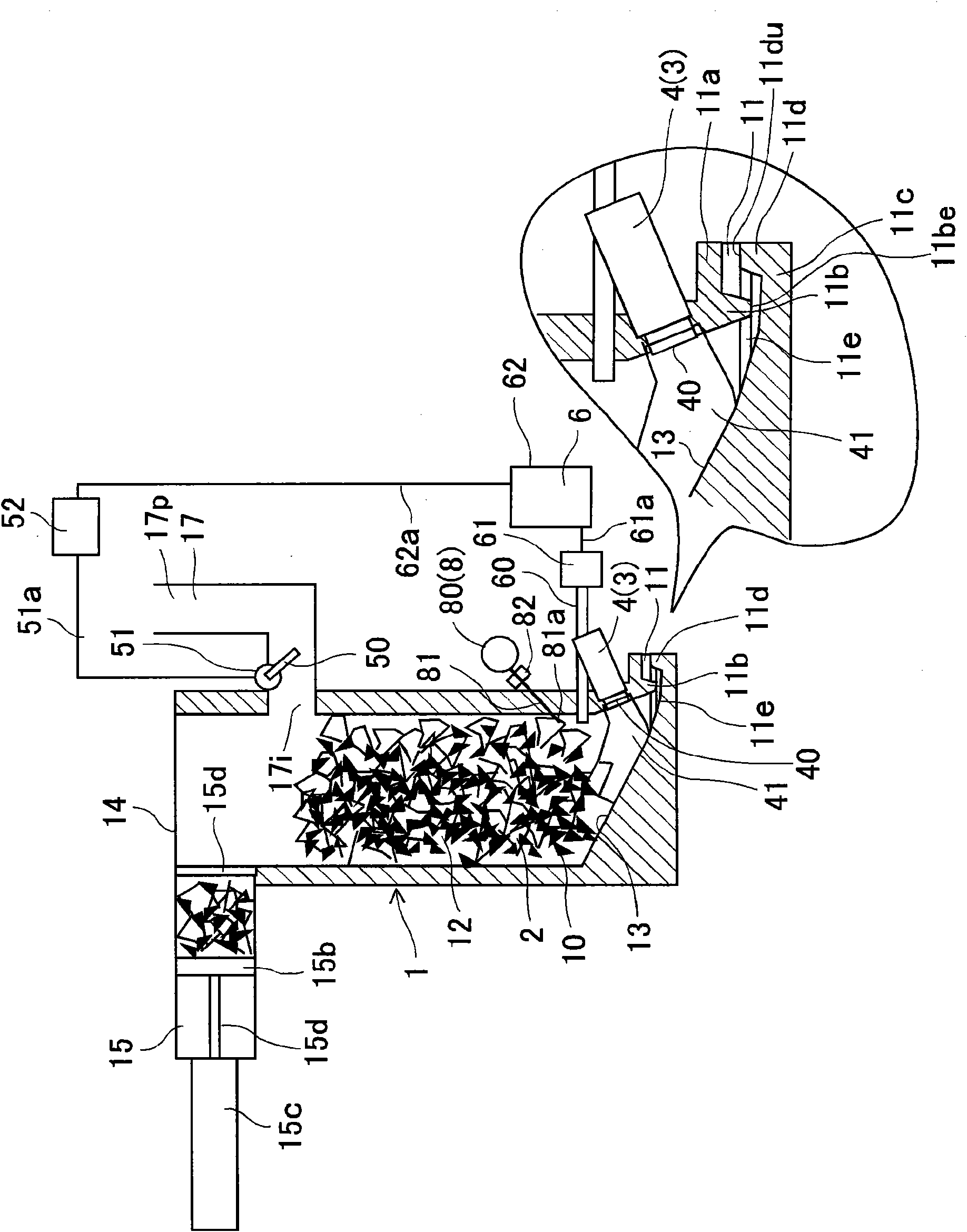
[0053] image 3 Embodiment 2 of this invention is shown. This embodiment basically has the same structure and effects as the above-mentioned embodiment. The melt outlet 11 includes an upper wall 11a, a lower wall 11c, a siphon partition wall 11b protruding downward from the upper wall 11a at the melt outlet 11, and an outlet intercepting portion protruding upward from the lower wall 11c. 11d, and the siphon liquid storage space 11e. In this way, the melt discharge port 11 is formed as an external air entry prevention structure capable of preventing external air from entering the melting chamber 10, and is a siphon structure, and the upper end 11du of the outlet blocking portion 11d is located closer to the lower end 11be of the siphon partition wall 11b than the lower end 11be of the siphon partition wall 11b. position above.

[0054] Since the melt stays in the siphon liquid storage space 11e and is held in this space, it is possible to improve the isolation and airtightne...

Embodiment approach 3

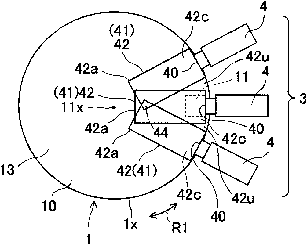
[0056] Figure 4 Embodiment 3 of this invention is shown. Figure 4 A cross-sectional view obtained by cutting the furnace body 1 in the horizontal direction is shown. like Figure 4 As shown, a plurality of burners 4 constituting the burner group 3 are arranged in a fan shape with respect to the center line 11x of the melting chamber 10 in the radial direction. The plurality of burners 4 are not arranged over the entire circumference in the circumferential direction (arrow R1 direction) around the center line 11x.

[0057] A hollow melting portion 42 having a cylindrical shape or a hollow shape similar to a cylinder is generated in the charge 2 of the melting chamber 10 by the combustion flame 41 discharged from the burner 4 . exist Figure 4 The hollow melting part 42 is roughly shown in . The burner 4 is arranged so that the front end portions 42a of the plurality of adjacent hollow melting portions 42 of the burner 4 overlap with each other.

[0058] As a result, whe...


PUM


Abstract

The invention provides a gas cupola for melting metal. The gas cupola is capable of melting a charge efficiently with the burning flames of combustion burners. The gas cupola comprises a furnace casing (1) having a melting chamber (10) and a molten metal discharge port (11) for discharging molten metal, and a plurality of combustion burners (4) for forming burning flames (41). The combustion burners (4) jet the burning flames (41) into a charge (2) in the melting chamber (10) to thereby melt the charge (2) in the melting chamber (10). Each of the combustion burners (4) creates a hollow moltenportion (42) having a hollow shape in the charge (2) in the melting chamber (10) with the burning flame (41) jetted out from each combustion burner (4). In a sectional view of the furnace casing (1) taken in a horizontal direction, the combustion burners (4) are arranged such that adjacent hollow molten portions (42) overlap each other. At the melting time of the charge (2), each hollow molten portion (42) and the molten metal discharge port (11) communicate with each other.

Description

technical field [0001] The invention relates to a gas-fired cupola for metal melting used for producing metal melts such as cast iron melts. Background technique [0002] Conventionally, there is known a coke cupola that melts charging materials such as pig iron by utilizing the heat of coke. In addition, in recent years, a gas-fired cupola for metal melting has been known, which has a burner capable of generating a combustion flame capable of melting a charged material from the viewpoint of efficient resource utilization and the like. In addition, there is also known a gas cupola for metal melting that uses both coke and a combustion flame from a burner (Patent Document 1). In addition, there is also known a metal melting furnace having a burner in a melting chamber of a furnace body (Patent Document 2). [0003] Patent Document 1: Japanese Patent Application Publication No. 57-27382 [0004] Patent Document 2: Japanese Patent Application Laid-Open No. 2000-274958 [00...

Claims


Application Information

Patent Timeline
Patent Type & Authority Applications(China)
IPC IPC(8): F27B1/10C21B11/02F27B1/08F27D17/00
CPCC21C5/562F27B1/08F27B1/10F27B1/28F27D3/04F27D17/001F27D19/00F27D21/00Y02P10/20
Inventor 鱼住稔戴槐生
Owner AISIN TAKAOKA CO LTD
Why Eureka
Try Eureka