Container for packaging nuclear waste with force-fitted lid

A container and solid waste technology, applied in the direction of portable protective containers, caps, pressure vessels, etc., can solve the problems of deterioration, damage, and impact on long-term storage safety, and achieve the effect of ensuring safety

Active Publication Date: 2011-05-04
ORANO RECYCLAGE
14 Cites 0 Cited by

AI-Extracted Technical Summary

Problems solved by technology

Pre-compression produces a compacted state that favors this result, but has the disadvantage that the compressed waste has a tendency to re-expand and exert considerable stress on the container and matrix
The situation is further aggravated by the release of gases from radiolysis that overpressure t...

Method used

[0043] Now refer to FIG. 6 for description. The closure member 6 may be welded to the side wall surface 2 via a back strip 21 at the junction with the side wall surface 2 . In addition, the closure member 6 (or the side wall surface 2) is provided with breathing pellets 22, w...

Abstract

The invention relates to a container that comprises a side wall (2) having end edges (3, 4) each provided with a blocking member (5, 6), wherein at least one of the latter is inserted for closing an opening. The peripheral outline (6c) of the inserted blocking member (6) and the inner outline (4a) of the end edge (4) associated with the side wall (2) have generally complementary shapes on at least a portion of the respective heights thereof, so that the inserted blocking member (6) can be fitted, on at least a portion of the height thereof, into the space defined by said end edge (4) of the side wall (2), and can bear on said end edge (4) by adjusting lugs (11) in recesses (10) having a complementary shape. The inclined joining walls define an angle of between 20 DEG and 40 DEG relative to the container axis.

Application Domain

Closure capsRefuse receptacles +2

Technology Topic

EngineeringMechanical engineering

Image

  • Container for packaging nuclear waste with force-fitted lid
  • Container for packaging nuclear waste with force-fitted lid
  • Container for packaging nuclear waste with force-fitted lid

Examples

  • Experimental program(1)

Example Embodiment

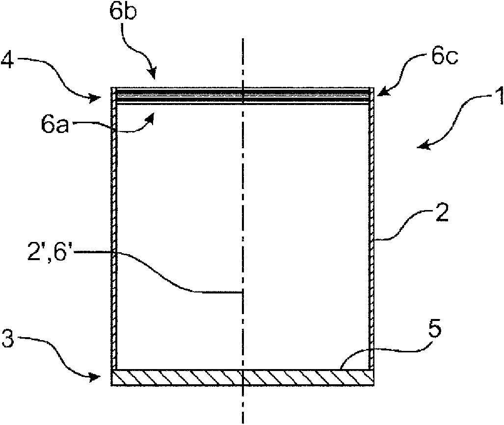
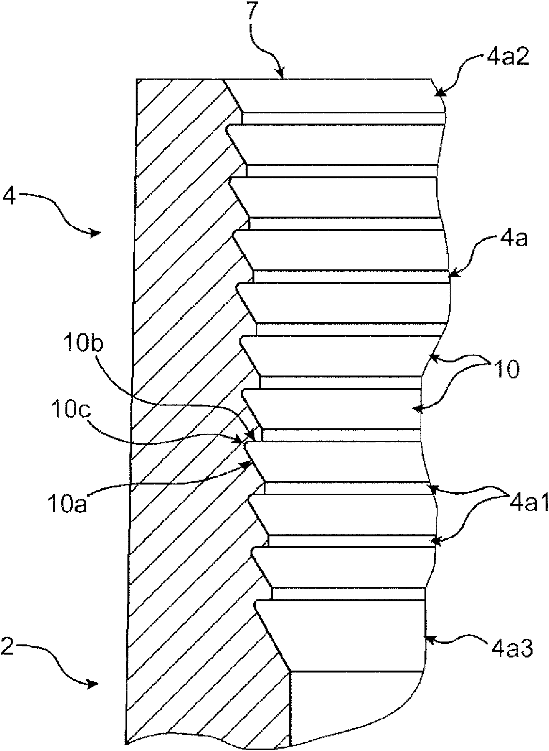
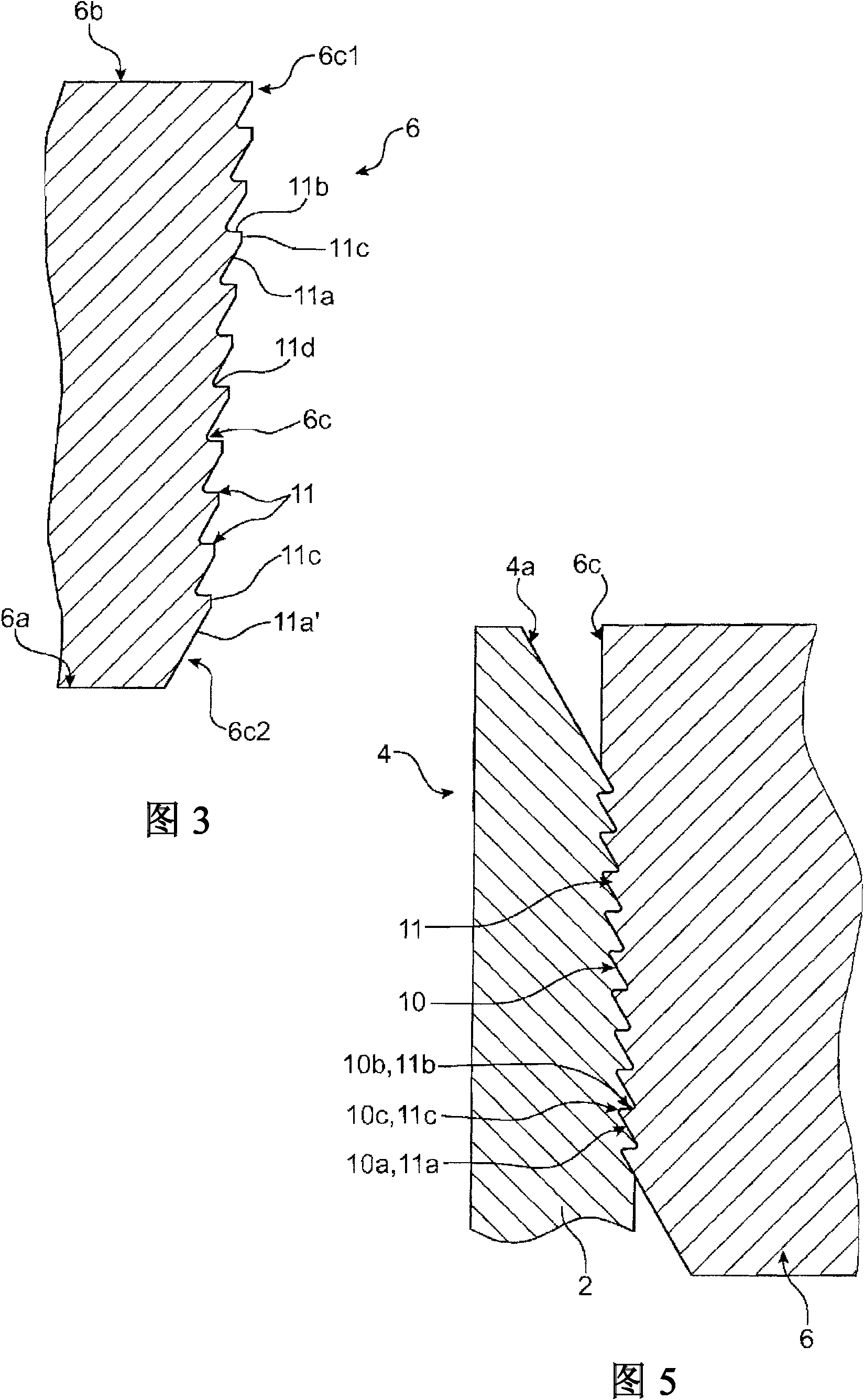
[0036] figure 1 The illustrated container 1 is particularly suitable for waste materials whose volume tends to increase or recover over a period of time. The container 1 is also particularly suitable for packaging stacked compressed blocks of radioactive waste. Such as figure 1 As shown, the container 1 is generally cylindrical barrel shape. It includes a cylindrical side wall 2 having two end edges, namely an upper end edge 3 and a lower end edge 4. The two end edges each have circular closing members 5 and 6, the lower closing member forms a bottom member, The closing member forms a lid. Here, the bottom member 5 is fixed to the side wall 2 non-removably, for example by welding or crimping. The cover member 6 is an embedded type. The cover member includes two surfaces: an inner surface 6a and an outer surface 6b, which are connected by an outer peripheral contour 6c. The lid 6 closes the upper opening 7 of the container 1 defined by the upper edge 4 of the side wall 2 ( figure 2 Or visible in Figure 4); as explained later, the waste material to be packaged and stored is filled into the container 1 through the upper opening 7, and then the lid 6 is set in place. The various parts of the container 1 are made of metallic materials, such as steel, but may also be made of any other materials selected according to environmental or operational constraints. The size and thickness of these parts of the container 1 can be configured by those skilled in the art as required.
[0037] The specific structural device used for the connection herein is located between the embedded cover 6 and the upper edge 4 of the side wall 2. These connection devices are particularly suitable for encapsulating radioactive waste. It really allows the lid 6 to be used to close the opening 7 of the container 1. The two components 1, 6 are kept connected by a very safe rigid connection system, which resists for example tens of metric tons of thrust (the waste compression block acts as a spring) and is safe The coefficient is very good. In this regard, on the one hand, such as figure 2 with image 3 As shown, the outer peripheral contour 6c of the embedded closing member 6 and the inner contour 4a of the upper end 4 of the side wall 2 have substantially complementary tapered shapes. After that, like figure 1 As shown in and 4, the embedded type closing member 6 (over its entire height) is accommodated and assembled in the space defined by the inner contour 4a of the upper end edge 4 (which defines the filling opening as described above), and abuts against the inner contour On 4a. On the other hand, the outer peripheral contour 6c of the embedded closure member 6 and the inner contour 4a of the upper end edge 4 of the side wall 2 are provided with a set of flanges and complementary grooves respectively extending on their respective circumferences. The number of pairs of flanges/grooves is specifically configured according to the force to be maintained. Specifically, these flanges and complementary grooves forming the structural means for connection can be nested with each other to provide positive and reverse locking for press-fitting the closure member 6 to the side wall 2. More accurately, such as figure 2 As shown, the inner contour 4a of the upper end 4 of the side wall 2 is provided with a set of annular parallel and continuous grooves 10 (the number in this article is 10) over its entire height, which together form a tooth-shaped section or so-called "wide "Pitch" (artillery pitch) (asymmetric thread) shape. The annular grooves 10 each extend on the one hand over the entire circumference of the inner contour 4a and on the other hand extend in a section perpendicular to the axis 2'of the side wall 2. The cross-section of each annular groove 10 is basically triangular, open in the direction of the axis 2', and includes an inclined annular surface 10a and an annular surface 10b forming a shoulder; here, these two surfaces 10a, 10b have a radial cross-section The annular joint surface 10c is connected. The inclined annular surface 10a is oriented upward (that is, toward the outside of the container) and is away from the axis 2'of the side wall 2 from bottom to top (that is, from the inside to the outside again); the annular shoulder 10b faces the lower end 3 of the side wall 2 (that is, toward The interior of the container) is oriented and extends along a plane perpendicular to the axis 2'of the side wall 2. The two continuous annular grooves 10 of the upper end edge 4 are separated by the annular portion 4a1 of the inner profile 4a. The annular portions 4a1 each extend perpendicular to the axis 2'of the side wall 2. figure 2 From bottom to top (ie again from the inside to the outside of the container), the groove 10 and the adjacent annular portion 4a1 deviate from the axis 2'toward the outer periphery; the annular portion 4a1 together defines the exact shape that is basically diffused from bottom to top Conical inner profile 4a. With respect to the groove 10, the inclined surface 10a extends at an included angle of 20° to 40° with respect to the axis 2'of the side wall 2. The width of the shoulder surface 10b is between 5 mm and 10 mm. The height of the annular portion 4a1 is between 5 mm and 10 mm. The radius of the portion 4a1 increases successively and regularly from bottom to top; thus, the inner contour 4a defines a truncated cone. Such as figure 2 As shown, the shape of the free upper end 4a2 of the inner contour 4a is basically a conical shape spreading from bottom to top. The groove 10 at the lower end 4a3 includes an inclined annular surface 10a' whose height is greater than the height of the other grooves 10 to compensate for the inner diameter of the side wall 2. On the other hand, such as image 3 As shown, the outer peripheral profile 6c of the embedded closure member 6 is provided with a series of mutually parallel annular flanges 11 over its entire height. The number in this article is 11. These annular flanges extend over the entire circumference and are each perpendicular to the axis. Extend in the plane of 6'. The annular flanges 11 form annular pawls, which abut each other at the height of the outer peripheral contour 6c. Together, these annular flanges form a substantially conical outer peripheral shape, and the cross-section is a rack or so-called "wide pitch" shape. These flanges 11 and the above reference figure 2 The grooves 10 are complementary. To this end, the respective shape of the flanges is basically a triangle formed by the inclined surface 11a, the inclined surface 11a is oriented toward the inner surface 6a and away from the axis 6'in the direction from the inner surface 6a to the outer surface 6b, and the surface 11b forms a flat surface, which It points to the side of the outer surface 6b and extends perpendicularly relative to the axis 6'of the closure member 6. Each flange 11 further includes a peripheral ridge 11c (connecting the aforementioned surfaces 11a and 11b), where the peripheral ridge is basically annular in shape and extends parallel to the axis 6'of the closure member 6 herein. The two continuous flanges 11 are further connected by an annular surface 11d, where the section of the annular surface is a circular arc or an arc with a radius. Specifically, these annular surfaces 11 collectively form and define the outer peripheral contour 6c of the closing member 6. The successive flanges 11 are offset from bottom to top toward the outer periphery; their annular ridges 11c together define a substantially conical space that spreads from the inner surface 6a to the outer surface 6b. After considering the gap, the shape and size of the flange 11 are the same as the above reference figure 2 The shape and size of the groove are consistent. The inclined surface 11a extends at an included angle of 20° to 40° with respect to the axis 6'of the closing member 6 (after considering the gap, the included angle is the same as that of the inclined surface 10); the width of the platform surface 11b is between 5 and 10 mm. In addition, the radius of each ridge 11c gradually increases with a length between 1 and 3 mm from bottom to top. For the groove 10, in this embodiment type, the flange 11 has protrusions (peripheral ridges 11c or inner contour 4a), and the radii of these protrusions are successively 20% to 50% of the width of the land surface 11b or the shoulder 10b The amount increased.
[0038] Therefore, the ridges 11c of the successive flanges 11 collectively define a truncated cone-shaped space spreading from the inner surface 6a to the outer surface 6b. In addition, the flange 11 located at the lower end 6c2 side of the outer peripheral profile 6c includes an inclined surface 11a' that is longer than the inclined surfaces of other flanges to facilitate the assembly of the closure member 6 to the side wall 2 as described below with reference to FIG. 4. Similarly, the radius of the outer peripheral ridge 11c of the flange 11 on the side of the inner surface 6a is smaller than the radius of the upper end 4a2 of the inner profile 4a of the side wall 2, especially for limiting the inner profile of the flange 11 and the side wall 2 in the following nesting operations Contact between 4a. Here, during the nesting operation, before the flange 11 of the closing member 6 is positioned in the final receiving groove 10, it can usually contact at most two to four annular portions 4a1 of the inner contour 4a. The cover 6 may undergo surface treatment, such as tempering, before being placed in place, so that its surface hardness is greater than that of the upper end 4 of the side wall 2, so as to avoid gripping during the following assembly operations.
[0039] The closing member 6 is set in place within the upper end 4 of the side wall 2 by the assembly or axial engagement of the compression device 15, which advantageously takes place according to the action steps (A, B, C) shown in FIG. 4. The installation compression device 15 includes: a base 16 on which the container 1 is positioned; a compacting skirt 17 to hold the embedded container 1 in place; and a cylinder (not shown) with the end of the rod 18 The part has a device 19 that can carry the closing member 6. The compression device 15 is further equipped with a set of devices (not shown) for manipulating and guiding the cylinder. In fact, as shown in FIG. 4a, the container 1 is placed on the base 16 with the filling opening 7 facing upwards, and the pressing skirt 17 is arranged around the side wall 2 of the container 1. Before the container 1 is positioned in the compression device 15 or after being placed in place in the compression device, the radioactive waste is filled into the container 1. At the same time, the closing member 6 is installed on the cylindrical holding device 19, that is, it is axially assembled to the container 1 through the opening 7 of the container 1 (see Fig. 4 again).
[0040] The waste material to be compressed and compacted has been shown. The waste material may be compressed blocks 20 that are pre-compressed and squashed, poured into metal drums in bulk. The height of the pressed skirt 17 is sufficient to accommodate the top of a stack of compressed blocks 20 beyond the side wall 2. Afterwards, the cylindrical rod 18 is axially manipulated toward the bottom member 5 of the container 1, so that the closing member 6 is arranged and fitted into the space defined by the upper edge 4 of the container 1 (such as Figure 4B Shown).
[0041] The cylinder 18 simultaneously compresses the stacked compression blocks 20 and makes it completely enter the container 1 by ensuring an optimal container filling rate.
[0042] The closing member 6 is manipulated to the final position defined by the corresponding mechanical stop at the junction advantageously with the cylinder at the top of the container; in fact, this final position corresponds on the one hand between the side wall 2 and the contour 4a and the contour 6c of the closing member 6 The engagement, on the other hand, corresponds to the operation of all grooves 10/flanges 11. The specific shape of all grooves 10/flanges 11 plays a role in optimizing the positioning of assembling the lid 6 to the container 1. During the axial translation of the closure member 6, the closure member can be used to compress and compact the product placed in the container 1. In a frame called "cold" or "forced" assembly, during the positioning of the cover 6, the upper edge 4 of the side wall 2 is elastically deformed to ensure that the flange 11 is finally fixed in the groove 10 of the side wall 2. In this case, the friction and engagement between the flange 11 and the upper end edge 4 of the side wall 2 can be restricted by the inclined surface 11 a of the flange 11. After the closing member 6 is properly assembled (as shown in Figure 4b), the holding device 19 can be removed from the closing member 6 and the pressing skirt 17 can be lifted to release the closed container 1 in which the packaged product remains in a compressed state. The embedded closure member 6 is held in place on the upper end 4 of the side wall 2 by the contact between the platform surface 11b of the flange 11 and the shoulder 10b of the groove 10. Figure 5 Another alternative embodiment of the outer contour of the side wall 2 and the closure member 6 passing through 4a, 6c is shown. Contour 4a, 6c and above reference Figure 1 to 3 Is very similar, the only difference is that it has a substantially cylindrical complementary shape (instead of Figure 1 to 3 Conical complementary shape in the illustrated embodiment). This shape of the connecting device between the side wall 2 and the closing member 6 is particularly advantageous for positioning the closing member 6 on the container 1 when the device for guiding the installation of the compression device is wider. In order to complete it in another alternative way, the outer peripheral profile 6c of the substantially cylindrical or conical closing member 6 may be provided with a substantially spiral flange at its height, and the peripheral ridge of the flange is also substantially cylindrical Or extend in a conical space. In this case, the spiral flange is matched with the spiral groove provided on the upper end 4 of the side wall 2. This type of cover 6 with a spiral flange is set in place by axial movement as described above with reference to FIG. 4 to apply the optimal compressive force to the processed product. In this case, the closing member 6 and the side wall 2 are advantageously provided with markings to allow accurate angular positioning therebetween, thereby accurately and completely positioning the spiral flange in the receiving groove. Generally and in all cases, the number and size of grooves and flanges are adjusted according to the stress that the closure member 6 will bear, especially according to the strength of the thrust applied by the packaged product. In addition, the structure of the bottom member 5 is generally similar to the above image 3 The structure is the same or similar. Side wall 2 lower end 3 and above reference figure 2 The upper edge 4 is the same or similar. In the case where the content is corrosive or liquid, the lower end 6c2 of the outer peripheral profile of the closure member 6 may be further provided with a rubber O-ring seal to ensure the sealing of the container and protect the flange/groove unit. Generally, the closing member 6 may be substantially cup-shaped or hemispherical before being assembled, with its dome portion oriented toward the inner surface 6a side. After being embedded in the container 1, under the thrust of the packaged product, the closure member 6 tends to be flattened and deformed, so that the diameter of the outer peripheral contour 6c is increased, and the fit of the flange 11/groove 10 is optimized.
[0043] Refer now Image 6 Be explained. The closing member 6 can be welded to the side wall surface 2 through a back strip 21 at the junction with the side wall surface 2. In addition, the closing member 6 (or the side wall surface 2) is provided with breathing pellets 22, which may include a porous material that can pass through. These settings can be used when it is necessary to measure or check the exhaust generated by the amplitude resolution of the container 1 in other ways, because they are concentrated in the position of the unit 22 and are therefore easy to control.
[0044] Will now explain Figure 7. The container 1 filled with the compression block 20 and closed may be temporarily or definitively set in, for example, the outer container 23 of the storage package. The outer container 23 may, for example, have a metal shell 27 and a cement layer 28 with radioactivity restriction, and include a main hollow portion 24 and a lid 25. It is not hermetically sealed, but instead allows the gas from the compression block 20 and passing through the container 1 to escape. The gas can pass through the body part 24 or the special part 26 provided on the cover 25 further including, for example, ventilation particles, a porous part or a labyrinth drill. The container 1 can be contained in the cavity of the outer container 23 with substantially no play. Since its size is sufficiently known and unchanged, there is almost no empty volume. After the container 1 is set in place, the lid 25 is welded to the body part 24 at the junction 29 with the body part 24.

PUM

no PUM

Description & Claims & Application Information

We can also present the details of the Description, Claims and Application information to help users get a comprehensive understanding of the technical details of the patent, such as background art, summary of invention, brief description of drawings, description of embodiments, and other original content. On the other hand, users can also determine the specific scope of protection of the technology through the list of claims; as well as understand the changes in the life cycle of the technology with the presentation of the patent timeline. Login to view more.
Why Eureka
Try Eureka