Motor vehicle chassis with anti-collision device

An anti-collision device and motor vehicle technology, applied in the direction of vehicle components, transportation and packaging, substructure, etc., can solve the problems of disappearance, casualties, energy consumption or partial consumption, etc., to improve the performance of anti-side collision, reduce Injury or death, good head and chest effects

Inactive Publication Date: 2011-05-11
凌建军
View PDF10 Cites 0 Cited by
  • Summary
  • Abstract
  • Description
  • Claims
  • Application Information

AI Technical Summary

Problems solved by technology

[0006] Why the anti-collision devices disclosed in these patents cannot be popularized and applied, its reason is to have the following problems:
[0007] 1) The body of the motor vehicle is in a compressed state during the collision process, and the front passenger compartment may disappear at high speed, which may endanger people's lives
[0008] 2) It can only absorb energy but not consume energy, that is, it cannot

Method used


Image

  • Motor vehicle chassis with anti-collision device
  • Motor vehicle chassis with anti-collision device
  • Motor vehicle chassis with anti-collision device

Examples


no. 1 approach

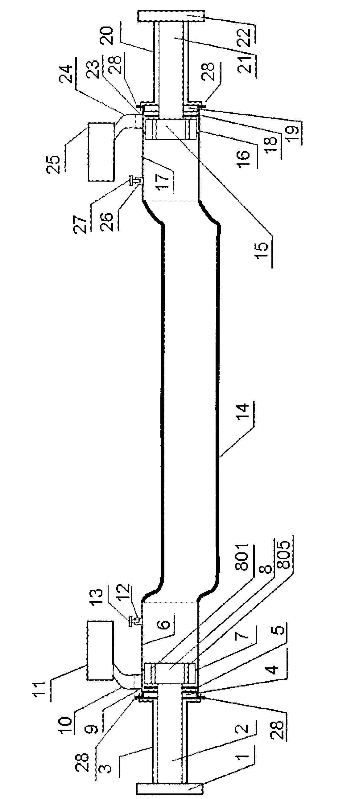
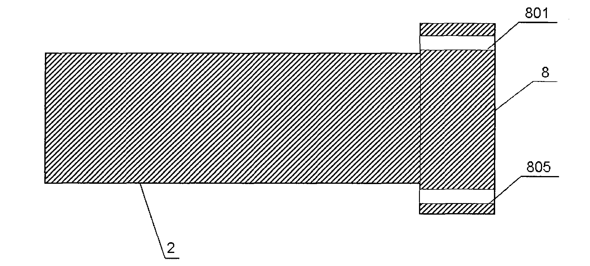
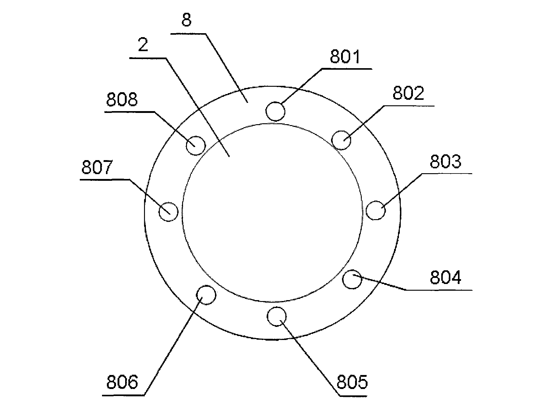
[0045] figure 1 It is a vertical sectional schematic diagram of a motor vehicle chassis with an anti-collision device of the present invention; figure 2 It is a sectional view of a piston and a piston ejector rod of a motor vehicle chassis with an anti-collision device of the present invention; image 3 It is a left view of a piston and a piston ejector rod of a motor vehicle chassis with an anti-collision device in the present invention; Figure 4 It is the right view of the piston and the piston ejector rod of a motor vehicle chassis with an anti-collision device in the present invention; Figure 5 It is a schematic top view of a motor vehicle chassis with an anti-collision device according to the present invention.

[0046] For ease of description, this application only describes a left part of a motor vehicle chassis with an anti-collision device, and the right part corresponds symmetrically to the left part. For brevity, the description of the right part thereof is om...

no. 2 approach

[0055] Figure 6 It is a schematic diagram of a second embodiment of a motor vehicle chassis with an anti-collision device according to the present invention. The second embodiment is basically the same as the first embodiment. Under the premise of the first embodiment, the first connecting pipe 10, the first buffer chamber 11, the second connecting pipe 24, and the second buffer chamber 25 are removed, and replaced with the first pressure relief sealing cover 33 and the second pressure relief chamber. Sealing cover 34.

[0056] When the front of the motor vehicle collides (assuming that the first anti-collision bar 1 is located at the front of the motor vehicle), the impact force first squeezes the first pre-tightening sleeve 3, and then the first anti-collision bar 1, the first anti-collision bar Piston push rod 2 moves backward together with the first piston 8 with injection holes (801, 802, 803, 804, 805, 806, 807, 808), and under the extrusion of first piston 8, the ene...

no. 3 approach

[0059] Figure 7 It is a schematic diagram of a third embodiment of a motor vehicle chassis with an anti-collision device according to the present invention. The third embodiment is basically the same as the first embodiment. On the premise of the first embodiment, the first connecting pipe 10 and the first buffer chamber 11 are removed and replaced with the first pressure relief sealing cover 33 .


PUM


Abstract

The invention discloses a motor vehicle chassis with an anti-collision device. The motor vehicle chassis comprises a tubular longitudinal beam, a piston cylinder, a piston, a piston mandril, a pressure relief tube, a piston cylinder end cover, an anti-collision rod and energy dissipation liquid, wherein one end of the piston cylinder is fixedly connected with the tubular longitudinal beam, and the other end is connected with the piston cylinder end cover; one end of the piston mandril is connected with the top of the piston, and the other end penetrates through the piston cylinder end cover to connect the anti-collision rod; the energy dissipation liquid is filled in the tubular longitudinal beam and the piston cylinder; the pressure relief tube is reserved on the piston cylinder; the piston is provided with at least one jet hole; the jet hole penetrates from the bottom of the piston to the top of the piston, so the tubular longitudinal beam is in a stretched state in an anti-collision process so as to prevent a passenger room from being extruded and deformed and prevent a steering column and a steering wheel from moving backwards to smash the heads and the chests of a passenger. Therefore, the security of a motor vehicle can be improved extremely.

Description

Technical field [0001] The invention relates to an active anti-collision method and device for a motor vehicle, in particular to a motor vehicle chassis with an anti-collision device. Background technique [0002] Since the advent of automobiles in 1886, while bringing convenience to human life and work, road traffic accidents have also caused a large number of casualties and property losses. So far, more than 34 million people have died in car accidents worldwide, while hundreds of millions of people have been injured or disabled. According to the "Global Status of Road Safety" report published by the World Health Organization (WHO) on June 15, 2009, the number of people involved in road traffic accidents in 2008 was as high as 1.2 million, and 20 million to 30 million people were injured or disabled. Annual economic losses due to road traffic accidents exceed $700 billion. [0003] The body of the existing motor vehicle is in a compressed state during the impact process....

Claims


Application Information

Patent Timeline
IPC IPC(8): B62D21/15
Inventor 凌建军杨铸黄鹂
Owner 凌建军
Why Eureka
Try Eureka