Gas spindle
A technology of air-floating spindles and spindles, which is applied in the direction of bearings, shafts, bearings, instruments, etc., can solve problems such as insufficient air buoyancy, unstable air source, and limited object load capacity, and achieve the goal of expanding the weight range and improving reliability Effect
- Summary
- Abstract
- Description
- Claims
- Application Information
AI Technical Summary
Problems solved by technology
Method used
Image

Examples
Embodiment 1
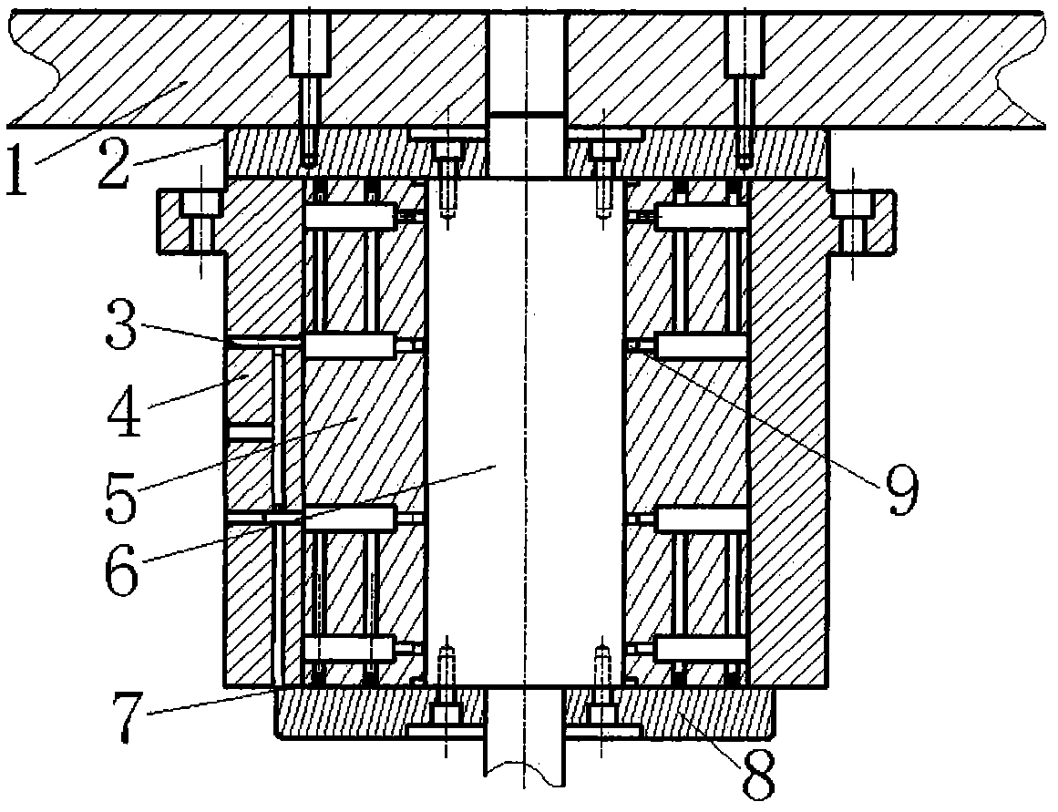
[0015] This embodiment is a large-load air bearing spindle applied to the Y901200D large-load roundness-waviness instrument. Including main shaft 6, upper end cover plate 2, lower end cover plate 8 and shaft sleeve parts.
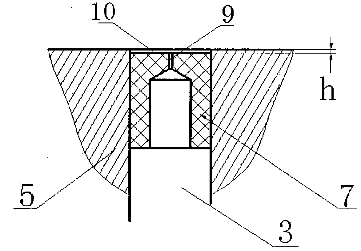
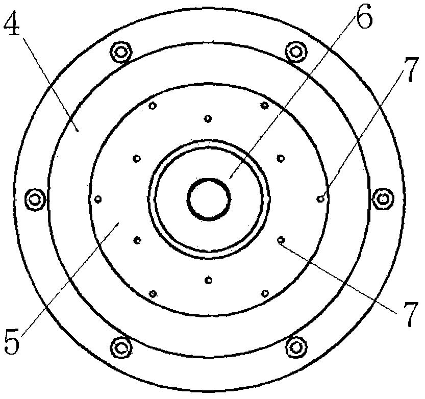
[0016] Both ends of the main shaft 6 are connected with an upper end cover 2 and a lower end cover 8 . A shaft sleeve composed of an outer sleeve 4 and an inner sleeve 5 is fitted on the main shaft 6, and the main shaft and the shaft sleeve are loosely fitted. The loading platform 1 is located above the upper end plate 2 and is fixedly connected with the upper surface of the upper end plate 2 . The lower end of the main shaft part is connected with the motor. There is an air passage connected between the outer jacket 4 and the inner sleeve 5, and the arrangement of the air passage adopts the prior art. A nozzle 7 is embedded at the end of each gas path.
[0017] Such as figure 1 As shown, there are two groups of annular uniformly distributed nozzles 7 ...
Embodiment 2
[0021] This embodiment is applied to the air bearing spindle of the Y9030D roundness-waviness instrument. Including main shaft 6, upper end cover plate 2, lower end cover plate 8 and shaft sleeve parts.
[0022] Both ends of the main shaft 6 are connected with an upper end cover 2 and a lower end cover 8 . A shaft sleeve composed of an outer sleeve 4 and an inner sleeve 5 is fitted on the main shaft 6, and the main shaft and the shaft sleeve are loosely fitted. The loading platform 1 is located above the upper end plate 2 and is fixedly connected with the upper surface of the upper end plate 2 . The lower end of the main shaft part is connected with the motor. There is an air passage connected between the outer jacket 4 and the inner sleeve 5, and the arrangement of the air passage adopts the prior art. A nozzle 7 is embedded at the end of each gas path.
[0023] Such as figure 1 As shown, there are two groups of annular uniformly distributed nozzles 7 on both ends of the...
Embodiment 3
[0027] This embodiment is applied to the air bearing spindle of the DY300 cylindricity measuring instrument. Including main shaft 6, upper end cover plate 2, lower end cover plate 8 and shaft sleeve parts.
[0028] Both ends of the main shaft 6 are connected with an upper end cover 2 and a lower end cover 8 . A shaft sleeve composed of an outer sleeve 4 and an inner sleeve 5 is fitted on the main shaft 6, and the main shaft and the shaft sleeve are loosely fitted. The loading platform 1 is located above the upper end plate 2 and is fixedly connected with the upper surface of the upper end plate 2 . The lower end of the main shaft part is connected with the motor. There is an air passage connected between the outer jacket 4 and the inner sleeve 5, and the arrangement of the air passage adopts the prior art. A nozzle 7 is embedded at the end of each gas path.
[0029] Such as figure 1 As shown, there are two groups of annular uniformly distributed nozzles 7 on both ends of ...
PUM
 Abstract
Description
Claims
Application Information
 - R&D
- Intellectual Property
- Life Sciences
- Materials
- Tech Scout
- Unparalleled Data Quality
- Higher Quality Content
- 60% Fewer Hallucinations
Browse by: Latest US Patents, China's latest patents, Technical Efficacy Thesaurus, Application Domain, Technology Topic, Popular Technical Reports.
© 2025 PatSnap. All rights reserved.Legal|Privacy policy|Modern Slavery Act Transparency Statement|Sitemap|About US| Contact US: help@patsnap.com