
Combustor capable of improving combustion intensity and heat transfer intensity by utilizing auxiliary counter-flow flames

A burner and heat transfer technology, which is applied to gas fuel burners, burners, combustion methods, etc., can solve the problems of heat intensity and flame temperature discount, unfavorable high-intensity effective heat exchange, and reducing the energy efficiency ratio of gas stoves. Uniform and consistent combustion reaction, rapid and intense combustion reaction, and the effect of improving transfer efficiency

Inactive Publication Date: 2011-05-11
李芳春
View PDF0 Cites 8 Cited by
  • Summary
  • Abstract
  • Description
  • Claims
  • Application Information

AI Technical Summary

Problems solved by technology

[0002] In the current fully premixed burner, all premixed gases work under the same pressure and flow rate, all combustion products have the same flow direction and flow trajectory, and the combustion conditions of all premixed gases are similar Or the same, all combustion flames and heat are not divided into main combustion and combustion-supporting. The disadvantage is that in order to stabilize the combustion flame, all premixed gases participate in the process of stabilizing the flame, and all premixed gases have components for stabilizing the flame. The possibility of contact, all combustion flames have the possibility of delayed output, so most burners will form a high-temperature combustion zone near the fire hole, which will not only easily ablate structural components, but also increase the mutual disturbance of combustion flames, resulting in The attenuation of air kinetic energy will reduce the ability of heat transfer. For gas stoves using flat heat exchange equipment, the volumetric heat intensity and flame temperature will be greatly reduced when heat is transferred to the heat exchange equipment, which is not conducive to effective high-intensity heat exchange. Heat will increase the probability of heat loss, which will reduce the energy efficiency ratio of the gas stove

Method used


Image

  • Combustor capable of improving combustion intensity and heat transfer intensity by utilizing auxiliary counter-flow flames
  • Combustor capable of improving combustion intensity and heat transfer intensity by utilizing auxiliary counter-flow flames
  • Combustor capable of improving combustion intensity and heat transfer intensity by utilizing auxiliary counter-flow flames

Examples


Embodiment 1

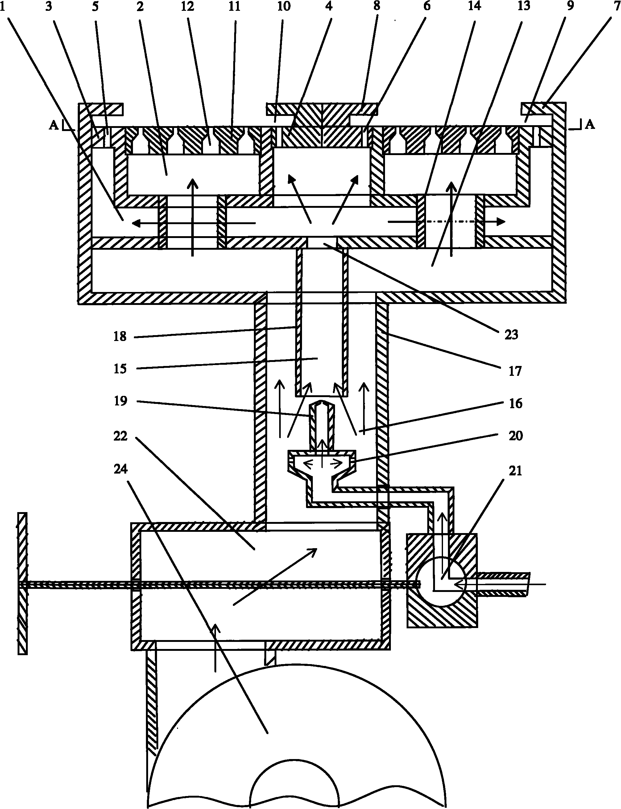
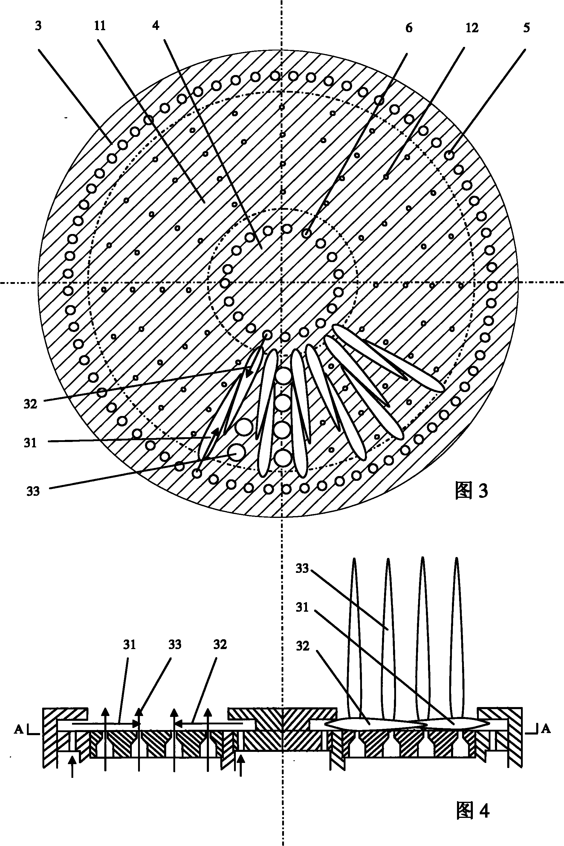
[0015] Such as figure 1 , image 3 , Figure 4 As shown, auxiliary burner 1, main combustion burner 2, auxiliary outer ring fire cover 3, auxiliary inner ring fire cover 4, outer ring fire cover fire hole 5, inner ring fire cover fire hole 6, outer ring rectification baffle 7 , the inner ring rectification baffle 8, the outer ring combustion diversion cavity 9, the inner ring combustion diversion cavity 10, the main burner cover 11, the main burner hole 12, the auxiliary mixed gas distribution chamber 1, the throat pipe 23, the main burner mix Gas distribution chamber 2, main combustion mixed gas chamber 13, main combustion mixed gas connecting pipe 14, secondary mixer 15, primary mixer 16, primary mixer mixing tube 17, secondary mixer injection pipe 18, secondary mixing Device gas nozzle 19, primary mixer gas nozzle 20, gas flow switching valve 21, air flow switching valve 22, blower 24.

[0016] It is characterized in that the auxiliary outer ring fire cover 3 , the main ...

Embodiment 2

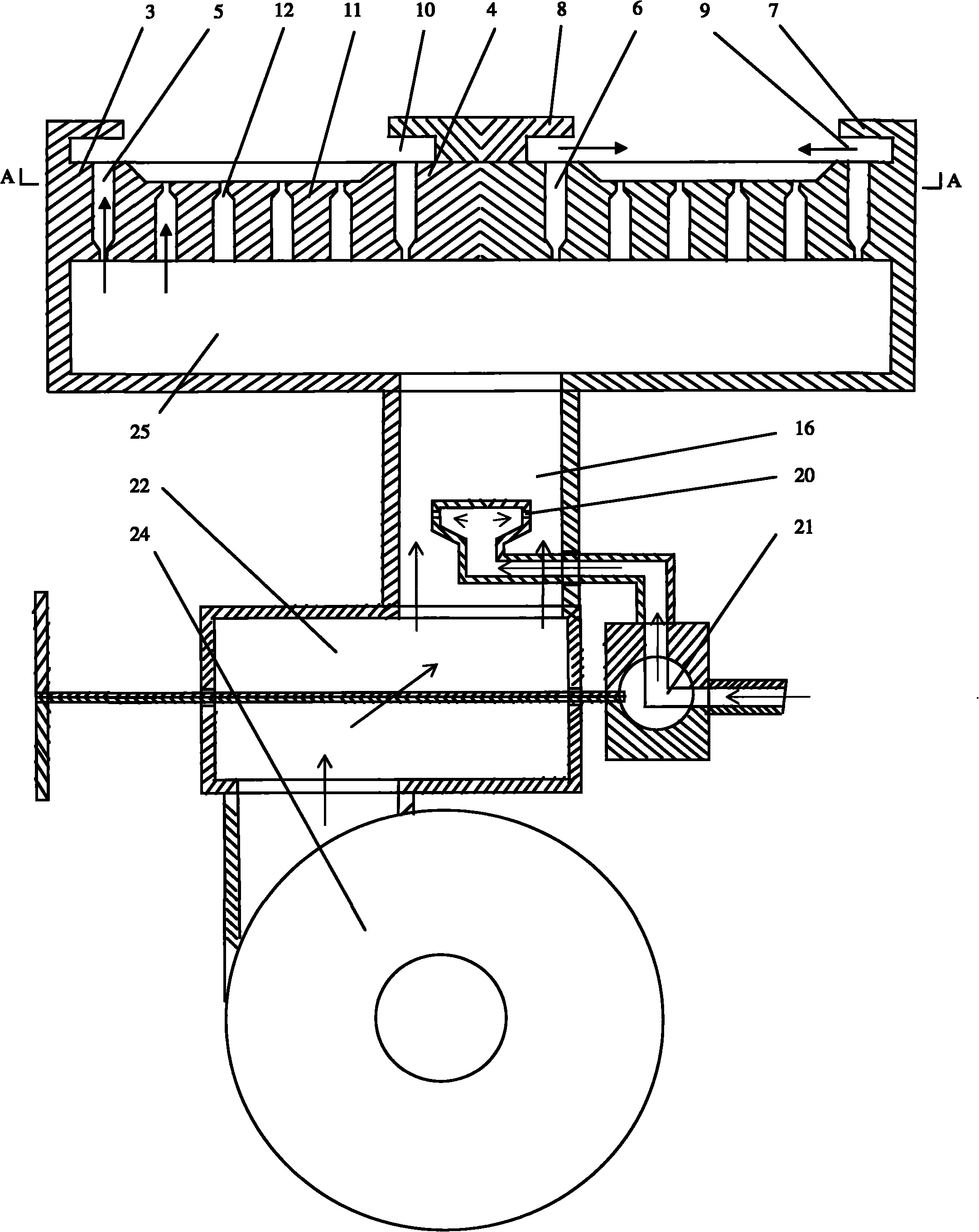
[0019] Such as figure 2 , image 3 , Figure 4 As shown, auxiliary outer ring fire cover 3, auxiliary inner ring fire cover 4, outer ring fire cover fire hole 5, inner ring fire cover fire hole 6, outer ring rectification baffle 7, inner ring rectification baffle 8, outer ring combustion Diversion cavity 9, inner ring combustion diversion cavity 10, main combustion cover 11, main combustion hole 12, mixed gas chamber 25, primary mixer 16, primary mixer gas nozzle 20, gas flow switching valve 21, air flow Switching valve 22, blower 24.

[0020] It is characterized in that the auxiliary outer ring fire cover 3 , the main burning fire cover 11 and the auxiliary inner ring fire cover 4 are tricyclic, and the main burning fire cover 11 is located between the auxiliary outer ring fire cover 3 and the auxiliary inner ring fire cover 4 . The auxiliary outer ring fire cover 3 is provided with an outer ring fire hole 5, and an outer ring rectification baffle 7 is arranged above the ...


PUM


Abstract

The invention discloses a combustor capable of improving combustion intensity and heat transfer intensity by utilizing auxiliary counter-flow flames, which comprises auxiliary fire holes and main combustion fire holes. The combustor is characterized in that: auxiliary outer-circle fire caps, main combustion fire caps and auxiliary inner-circle fire caps are arranged to form a three-circle shape; the main combustion fire caps are positioned between the auxiliary outer-circle fire caps and the auxiliary inner-circle fire caps; an annular cavity between the auxiliary outer-circle fire cap and a corresponding outer-circle rectifier baffle plate is an outer-circle combustion diversion cavity; the annular cavity between the auxiliary inner-circle fire cap and a corresponding inner-circle rectifier baffle plate is an inner-circle combustion diversion cavity; and an opening of the outer-circle combustion diversion cavity is opposite to the opening of the corresponding inner-circle combustion diversion cavity. Outer-circle auxiliary flames flow relative to inner-circle auxiliary flames to form flame nets with more uniformly distributed heat on the surfaces of the main combustion fire caps, so that main combustion premixed gases flowing out of each gas orifice can obtain enough heat required by combustion, the combustion reaction of all the main combustion premixed gases is uniform, consistent and sufficient, and the combustion flames are stable. The main combustion premixed gases flow out at high flow rate and under high pressure, so the combustion intensity and flame temperature of the main combustion premixed gases are correspondingly high. Main combustion flames entrain the auxiliary flames by high kinetic energy to simultaneously transfer the heat, and the high-efficiency heat transfer can make the high temperature combustion flames rapidly reach the bottom of a roasting kettle.

Description

Technical field: [0001] The invention relates to a combined gas burner, which can be equipped on gas equipment such as heating furnaces and gas stoves. Background technique: [0002] In the current fully premixed burner, all premixed gases work under the same pressure and flow rate, all combustion products have the same flow direction and flow trajectory, and the combustion conditions of all premixed gases are similar Or the same, all combustion flames and heat are not divided into main combustion and combustion-supporting. The disadvantage is that in order to stabilize the combustion flame, all premixed gases participate in the process of stabilizing the flame, and all premixed gases have components for stabilizing the flame. The possibility of contact, all combustion flames have the possibility of delayed output, so most burners will form a high-temperature combustion zone near the fire hole, which will not only easily ablate structural components, but also increase the mu...

Claims


Application Information

Patent Timeline
Patent Type & Authority Applications(China)
IPC IPC(8): F23D14/00F23D14/02F23D14/46F23D14/58
Inventor 李芳春
Owner 李芳春
Learn More