
Hydrogen reactor

A hydrogen production reactor and reactor technology, applied in the direction of hydrogen, electrochemical generators, chemical instruments and methods, etc., can solve the problems of difficult heat supply, low output power, low thermal efficiency, etc.

Active Publication Date: 2019-03-08
KOREA INST OF ENERGY RES
View PDF3 Cites 0 Cited by
  • Summary
  • Abstract
  • Description
  • Claims
  • Application Information

AI Technical Summary

Problems solved by technology

However, this methanol reformer has disadvantages that the size of the reactor as a whole is large, that the combustion catalyst does not completely contact the side of the reforming catalyst, and that the combustion catalyst is not filled in one tube but dispersedly filled in multiple places. , making it difficult to efficiently supply heat to the reformer
However, this small methanol steam reforming device has the following disadvantages: it has a relatively low output power of about 200 mW, and in order to maintain the reaction temperature, a large amount of fuel, that is, methanol, is put into the burner, so that the overall thermal efficiency is very low. 5 to 10%

Method used


Image

  • Hydrogen reactor
  • Hydrogen reactor
  • Hydrogen reactor

Examples


Embodiment 1

[0153] The reforming part is filled with a copper (Cu) component catalyst made in the shape of a tray with an average diameter of 1.5mm as a reforming catalyst, and the combustion part is filled with platinum (Pt) made in a ceramic honeycomb shape. )catalyst. The preheating pipe uses 1 / 8-inch pipe, and winds the outside of the reforming section into a coil shape at equal intervals according to the height, so that the vaporized reforming material is further preheated by the heat supplied by the reforming section on the outer wall.

[0154] As a raw material, a liquid fuel prepared by mixing 60% by weight of methanol and 40% by weight of distilled water on a mass basis was used. In addition, the same liquid fuel is used for the heating raw material and the reforming raw material. As a reforming raw material, the liquid fuel was supplied at 7.8 g / min. The heating raw material is supplied at a flow rate of 2.9g / min. For combustion, the Air is supplied at the same time as the f...

Embodiment 2

[0158] The reforming part is filled with a copper (Cu) component catalyst manufactured in the shape of a tray with an average diameter of 1.5mm as a reforming catalyst, and the combustion part is filled with platinum ( Pt) catalyst. The preheating pipe uses 1 / 8-inch pipe, and winds the outside of the reforming section into a coil shape at equal intervals according to the height, so that the vaporized reforming material is further preheated by the heat supplied by the reforming section on the outer wall. In addition, a catalyst composed of ruthenium (Ru) produced in a tray shape with an average diameter of 1.5 mm was filled in the carbon monoxide removal unit at the end of the reformer unit.

[0159] As a raw material, a liquid fuel prepared by mixing 60% by weight of methanol and 40% by weight of distilled water on a mass basis was used. In addition, the same liquid fuel is used for the heating raw material and the reforming raw material. As a reforming raw material, the liq...


PUM

PropertyMeasurementUnit
diameteraaaaaaaaaa

Abstract

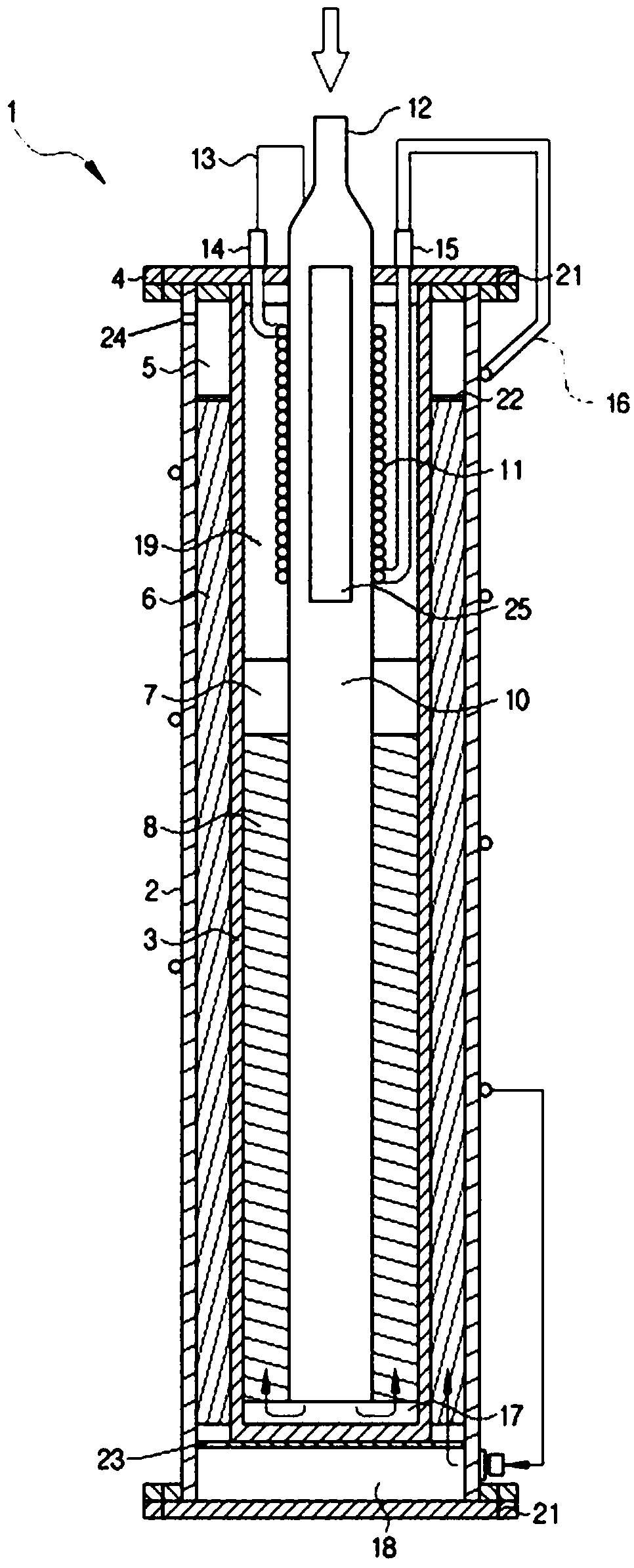
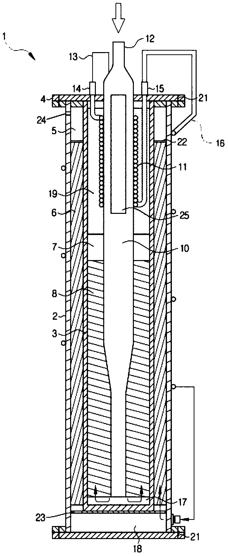
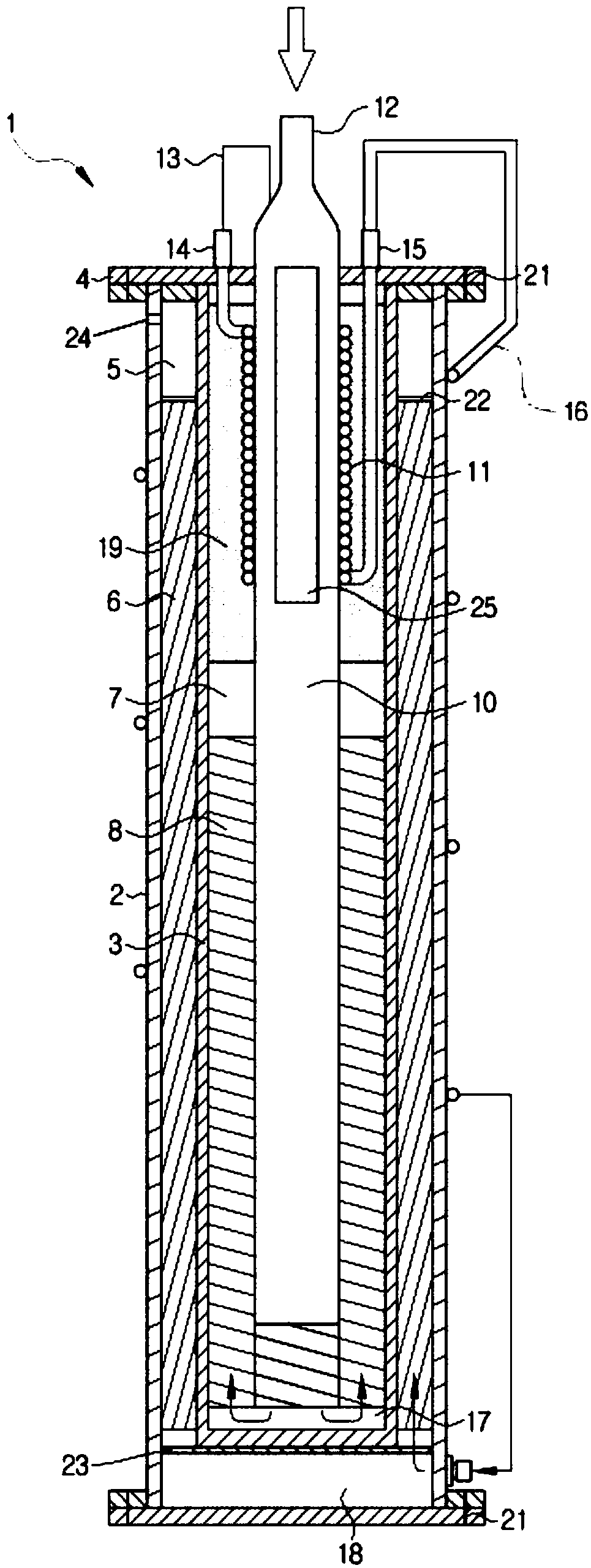
The present invention relates to a reactor for producing a reformed gas containing hydrogen by a raw material containing a carbon compound and water, the reactor comprising: a reforming unit for reforming the raw material to produce a reformed gas containing hydrogen; a combustion unit supplying heat to the reforming unit by burning the raw material; a carbon monoxide removal reaction section for removing carbon monoxide in the reformed gas containing hydrogen; a heated raw material feeding pipe; and a reformed raw material phase change tube which is located in the combustion unit and used for heating the raw material. A first housing, a second casing, and the heated raw material feed pipe are provided in this order from the outside in a concentric structure, and the reforming unit and the combustion unit are respectively and independently formed by the space between the first housing and the second housing and the space between the second housing and the heated raw material feed pipe.

Description

technical field [0001] The present invention relates to a hydrogen production reactor which reforms carbon compounds into reformed gas containing hydrogen and supplies it to a fuel cell. Specifically, it relates to a hydrogen production reactor for producing hydrogen from carbon compounds by evaporating the raw material gasified in the phase change part of the liquid raw material mixed with carbon compounds and water in a reforming reaction part filled with a catalyst In order to promote the reaction, a combustion reaction part is set on the adjacent flow path separated from the reforming reaction part, and a part of the liquid raw material is induced to carry out combustion reaction on the catalyst, so that the heat generated by the combustion reaction It is supplied to the reforming reaction part as reaction heat. Background technique [0002] In recent years, as concerns about environmental issues have increased, interest and demand for clean fuels fueled by hydrogen hav...

Claims


Application Information

Patent Timeline
Patent Type & Authority Patents(China)
IPC IPC(8): C01B3/32C01B3/22H01M8/0612H01M8/0668
CPCB01J2219/00018C01B3/22C01B3/326C01B2203/0233C01B2203/0244C01B2203/0277C01B2203/0283C01B2203/066C01B2203/0811C01B2203/1223C01B2203/84H01M8/0618H01M8/0668Y02E60/50
Inventor 徐东柱黄英在郑云浩尹旺来朴相浩金宇铉具己暎
Owner KOREA INST OF ENERGY RES
Learn More