
Design method of synchrotron radiation curved-edge focusing mirror with maximum application range

A technology of scope of application and focusing mirror, which is applied in the field of synchrotron radiation optics and beamline engineering of synchrotron radiation, can solve problems such as the inability to change the focusing mirror with curved edges, and achieve the effects of maximizing the scope of application, optimizing precision, and eliminating surface shape errors

Active Publication Date: 2012-06-27
INST OF HIGH ENERGY PHYSICS CHINESE ACAD OF SCI
View PDF0 Cites 0 Cited by
  • Summary
  • Abstract
  • Description
  • Claims
  • Application Information

AI Technical Summary

Problems solved by technology

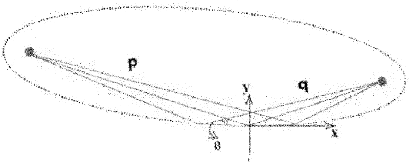
[0028] The purpose of the present invention is to provide a method for obtaining a synchrotron radiation curved edge bending focusing mirror with the largest applicable range, so as to solve the existing method that can only realize the bending surface shape under the specific focusing conditions of the design, which is no surface error The ideal ellipse, but can not realize the curved edge focusing lens can adapt to the problem that the focusing conditions change in a large range

Method used


Image

  • Design method of synchrotron radiation curved-edge focusing mirror with maximum application range
  • Design method of synchrotron radiation curved-edge focusing mirror with maximum application range
  • Design method of synchrotron radiation curved-edge focusing mirror with maximum application range

Examples


Embodiment Construction

[0053] The present invention will be described in further detail below in combination with embodiments and specific embodiments.

[0054] The basic idea of ​​the present invention is: the bending moment distribution relative slope design value k Md It will affect the size of the total remaining surface shape error when the focusing condition changes, that is, it will affect the application range of the focusing mirror when the focusing condition p, q or θ deviates from the design value. By taking the appropriate k Md , so that the absolute value of the derivative of the root mean square error of the remaining surface shape error after the bending moment adjustment to the focusing condition p, q or θ is the smallest, so that the remaining surface shape error is the smallest near the design focusing condition. Therefore any invention utilizing this idea should belong to the protection scope of the present invention.

[0055] As mentioned above, the curved edge bending mirror h...


PUM


Abstract

The invention discloses a method for obtaining a synchrotron radiation curved-edge bent focusing mirror with the maximum application range, which comprises the following steps: establishing an ideal elliptical mirror surface equation under focusing conditions; establishing a mirror body bending flexibility differential equation to obtain an inertia moment distribution design function meeting the requirement that the shape of the bent surface is an ideal ellipse, wherein the function contains a bending moment distribution relative slope design value kMd to be designed; when the focusing conditions deviate from the design value, calculating and adjusting the bending moment of the focusing mirror to deviate from the design value so as to be adapted to the variation of the focusing conditions; and calculating the error mean square root of the total remaining surface shape after the bending moment is adjusted, solving the kMd value which allows the absolute value of the mean square root to the derivative with respect to a certain focusing condition is minimum, then substituting the kMd value into the inertia moment distribution design function to obtain the geometric design of the mirror body optimized according to the focusing condition; and determining the focusing mirror parameters and bending the focusing mirror according to the calculation result. When the focusing condition is changed, the focusing mirror disclosed by the invention can greatly eliminate the surface shape error by adjusting the bending moment, thereby maximizing the application range of the curved-edge bent focusing mirror with respect to a certain focusing condition.

Description

technical field [0001] The invention relates to a method for obtaining a synchrotron radiation curved-edge bending focusing mirror with a maximum application range, and belongs to the technical fields of synchrotron radiation beamline engineering and synchrotron radiation optics. Background technique [0002] One of the advantages of synchrotron radiation is its high brightness. Brightness generally refers to the photon number density in the phase space. The high photon flux of synchrotron radiation and the small volume of the phase space create the characteristics of high brightness. According to Liu Wei's theorem, the brightness cannot be increased without sacrificing the photon flux. When the line width of a beam is compressed, its angular width increases; conversely, when the angular width is compressed so that the beam becomes more collimated, its line width increases. However, different experiments have different requirements on the shape of the phase space of the be...

Claims


Application Information

Patent Timeline
Patent Type & Authority Patents(China)
IPC IPC(8): G02B19/00G02B27/00G02B5/10
Inventor 李明盛伟繁刘鹏
Owner INST OF HIGH ENERGY PHYSICS CHINESE ACAD OF SCI
Learn More