
Ultra-precision processing tool and processing method for optically complex surface of single crystal silicon

An ultra-precision machining, complex surface technology, applied in optical surface grinders, manufacturing tools, metal processing equipment, etc., can solve the problems of low precision and low processing efficiency, achieve high manufacturing precision, good surface quality, wear resistance good effect

Active Publication Date: 2020-06-12
HARBIN INST OF TECH
View PDF5 Cites 0 Cited by
  • Summary
  • Abstract
  • Description
  • Claims
  • Application Information

AI Technical Summary

Problems solved by technology

[0004] The present invention provides an ultra-precision processing tool and processing method for the optically complex surface of single crystal silicon to solve the problems of low processing efficiency and low precision of the existing ultra-precision processing technology for optically complex surfaces of single crystal silicon

Method used


Image

  • Ultra-precision processing tool and processing method for optically complex surface of single crystal silicon
  • Ultra-precision processing tool and processing method for optically complex surface of single crystal silicon
  • Ultra-precision processing tool and processing method for optically complex surface of single crystal silicon

Examples


specific Embodiment approach 1

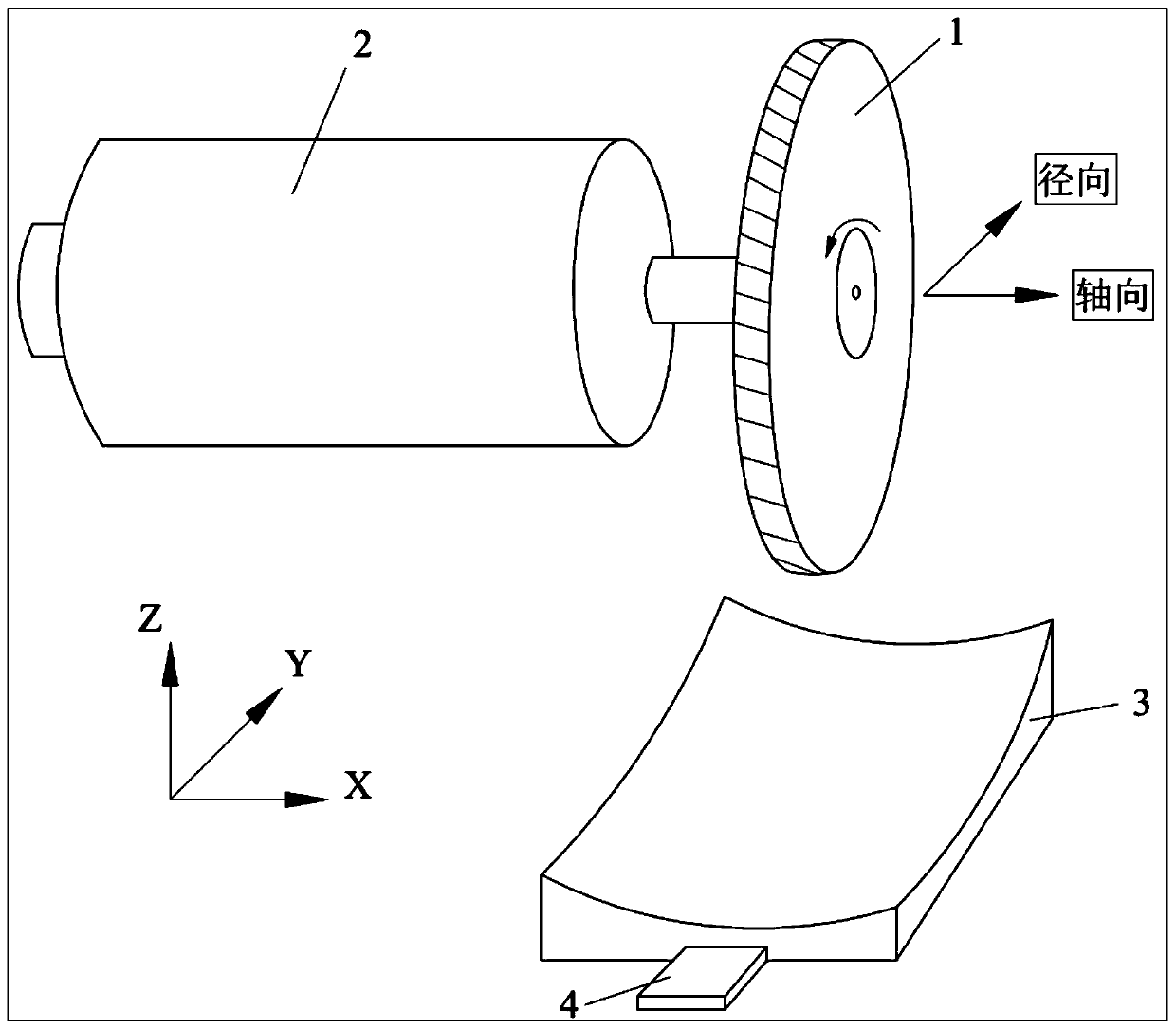
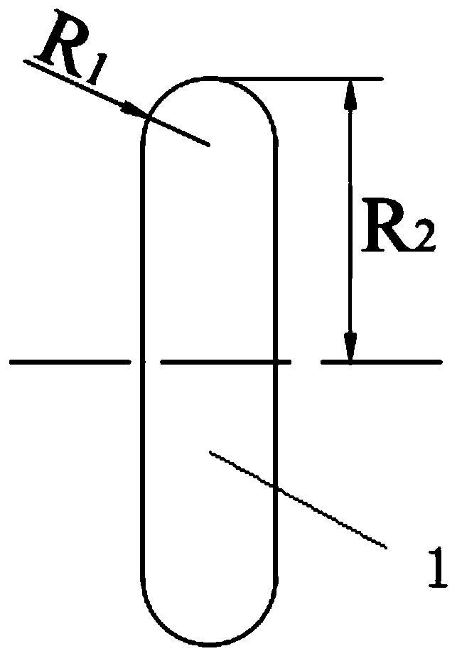
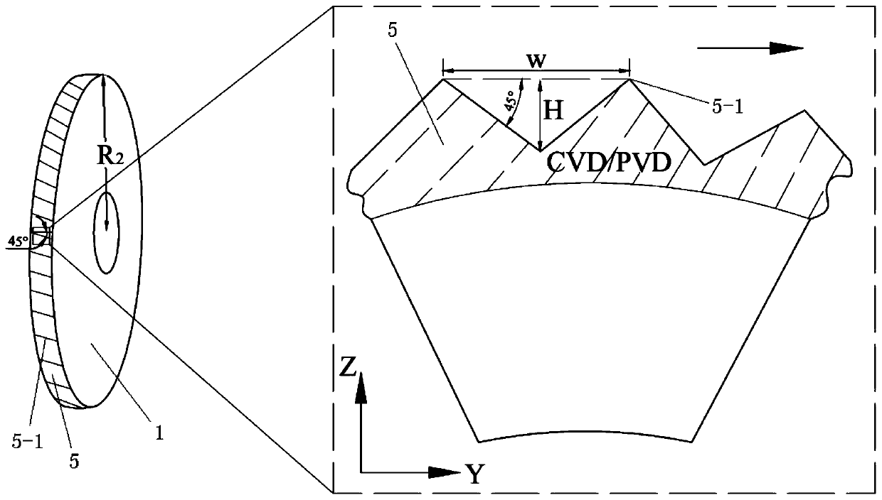
[0026] Specific embodiment one: combination figure 1 , figure 2 , image 3 To explain this embodiment, this embodiment provides an ultra-precision machining tool for a complex optical surface of monocrystalline silicon. The machining tool 1 is in the shape of a disc, and the radius of the disc is R 2 ; The side circumference of the processing tool is a 180° fillet, and the fillet radius is R 1 ,Such as figure 2 Shown; the processing tool is provided with a through hole at the center of the circle, the through hole is used to mount the processing tool 1 to the rotating shaft 2 of the processing machine, R 1 Smaller than the minimum radius of curvature r of the surface structure of the single crystal silicon optically complex surface element 3 1 ; R 2 Smaller than the minimum curvature radius r on the single crystal silicon optically complex surface element 3 1 The minimum radius of curvature r in the other direction perpendicular to the direction 2 ;Such as image 3 As shown, the ...

specific Embodiment approach 2

[0041] Specific embodiment two: this embodiment is different from specific embodiment one in that the side surface of the processing tool is provided with a CVD or PVD diamond thin film coating with a thickness of 3-5 μm; the CVD means chemical vapor deposition ( Chemical Vapor Deposition), the PVD stands for Physical Vapor Deposition.

[0042] The other steps and parameters are the same as in the first embodiment.

specific Embodiment approach 3

[0043] Specific implementation mode three: combination figure 1 , Figure 4 , Figure 5 To describe this embodiment, the ultra-precision processing method for the optically complex surface of single crystal silicon provided in this embodiment specifically includes the following steps:

[0044] Step 1. Install the processing tool on the rotating shaft of the processing machine with an installation error of less than 1μm; install the trial-machined part horizontally on the worktable; use the processing tool to perform trial-processing on the trial-machined part, using radial feed and shaft Two cross-arc grooves are machined on the surface of the trial-machined part by the forward feeding method; the axial direction refers to the direction of the rotation axis of the processing machine tool, and the radial refers to the direction of the rotation axis of the processing machine The direction perpendicular and parallel to the horizontal plane; after trial processing, the surface accurac...


PUM

PropertyMeasurementUnit
thicknessaaaaaaaaaa

Abstract

The invention provides an ultra-precision machining tool for monocrystalline silicon optical complex surface and a machining method thereof, and belongs to the technical field of ultra-precision machining. The method comprises the following steps of carrying out test processing on a test piece by utilizing a machining tool firstly, detecting the surface shape precision of the two cross-shaped cross arc grooves respectively on the surface of the test piece after the test is performed, and accurate R2 and R1 values are obtained; then, data calculation is carried out on the polynomial or the discrete point cloud which is used for describing monocrystalline silicon optical complex surface elements, obtaining the three-dimensional rectangular data under a machine tool coordinate system, then performing machining trajectory planning according to the three-dimensional rectangular data, R2 and R1; finally, processing the monocrystalline silicon optical complex surface element according to themachining trajectory. The method solves the problems that an existing ultra-precision machining technology for monocrystalline silicon optical complex surfaces is low in processing efficiency and lowin precision, the method can be used for ultra-precision processing of surfaces of various hard and brittle refractory materials such as glass, ceramics, crystals.

Description

Technical field [0001] The invention relates to an ultra-precision processing tool and a processing method for optically complex surfaces of hard and brittle materials, and belongs to the technical field of ultra-precision processing. Background technique [0002] Driven by the application requirements of infrared imaging technology, the demand for ultra-precision machining of monocrystalline silicon optical complex surfaces (including off-axis aspheric surfaces, free-form surfaces and structural surfaces) is increasing. At present, the traditional manufacturing process for the optically complex surface of monocrystalline silicon requires a series of processes such as milling, fine grinding, grinding, and polishing. However, due to the large number of processes in the processing process, it is necessary to repeatedly install processing tools or workpieces, which not only increases the auxiliary time for forming processing, but also brings about larger installation errors, greatly...

Claims


Application Information

Patent Timeline
Patent Type & Authority Patents(China)
IPC IPC(8): B24B13/00B24B13/01
CPCB24B13/00B24B13/01
Inventor 郭兵王生张俊赵清亮尹航
Owner HARBIN INST OF TECH
Learn More