Three-dimensional imaging device and system

An imaging device and three-dimensional technology, applied in three-dimensional systems, image communication, optics, etc., can solve problems such as size distortion, limited number of layers of three-dimensional scenes, discounts for restoring the true degree of three-dimensional scenes, etc., to achieve cost savings and good visual effects , The effect of low system cost

Inactive Publication Date: 2011-05-11
刘武强
View PDF1 Cites 28 Cited by
  • Summary
  • Abstract
  • Description
  • Claims
  • Application Information

AI Technical Summary

Problems solved by technology

[0004] In this patent, a problem that arises in such an arrangement of the displays is: if the sizes of the displays are the same, and each two-dimensional layer is made according to the size of a real three-dimensional scene during production, and the image of each two-dimensional layer The distance from the human eye is farther than the distance between the real two-dimensional layers and the human eye, so because of the viewing distance, the image of each two-dimensional layer seen by the human eye is larger than the real two-dimensional layer seen by the human eye If it is smaller, the image will be distorted. In order to eliminate the size distortion caused by the distance between the two groups of plane display units, the size of the two-dimensional plane dis

Method used


Image

  • Three-dimensional imaging device and system
  • Three-dimensional imaging device and system
  • Three-dimensional imaging device and system

Examples


Embodiment Construction

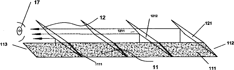
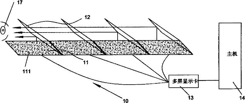
[0031] The invention relates to a three-dimensional imaging device and system. The present invention is an improved invention based on the patent application number: 200910109909.X Chinese Invention Patent. The difference from this patent is that the centers of the two-dimensional displays of the three-dimensional imaging device of the present invention are on a straight line , each semi-reflective and semi-transparent optical device is arranged between two two-dimensional displays, and the reflective surfaces of each semi-reflective and semi-transparent optical device are parallel to each other, and the straight line formed by the center of each two-dimensional display and the reflection of the semi-reflective and semi-transparent optical device face vertical. With such a design, an infinite number of two-dimensional displays can be set along a straight line, so that the original three-dimensional scene can be divided into infinite parts, and the combined image of the three-d...


PUM


Abstract

The invention belongs to the technical field of three-dimensional imaging, in particular relates to a three-dimensional imaging device and system. The three-dimensional imaging device comprises a display unit and a polarizing device, and is characterized in that: the display unit comprises a plurality of two-dimensional displays; each two-dimensional display comprises a display window; display windows of various two-dimensional displays are in the same size and shape; centers of the display windows of the two-dimensional displays are in a straight line; the polarizing device comprises a plurality of semireflecting and semi-transparent optical elements; a semireflecting and semi-transparent optical element is arranged between every two two-dimensional displays; a semireflecting and semi-transparent optical element is respectively arranged on the head and/or the tail of a two-dimensional display row formed by a plurality of the two-dimensional displays; reflecting surfaces of the various semireflecting and semi-transparent optical elements are in parallel to each other; the straight line formed by the connection of the centers of the two-dimensional displays is perpendicular to the reflecting surfaces of the semireflecting and semi-transparent optical elements; and the area of the reflecting surfaces of the semireflecting and semi-transparent optical elements is 1.414 to 2 times that of the display windows of the two-dimensional displays.

Description

【Technical field】 [0001] The invention belongs to the technical field of three-dimensional imaging, and relates to a three-dimensional imaging device and system. 【Background technique】 [0002] The most fundamental difference between 3D display and 2D display is that various methods should be used to bring visual depth perception to the viewer, so that people can naturally or unnaturally obtain the third-dimensional information in the picture. For 3D stereoscopic imaging technology, it is very important to restore the real physical depth of field in 3D stereoscopic space, and it is also the most critical factor for human eyes to perceive 3D stereoscopic images. [0003] The inventor previously introduced a three-dimensional imaging method in the Chinese invention patent with the patent application number 200910109909.X. The method is to longitudinally divide the three-dimensional scene into several two-dimensional layers according to the depth of the physical scene, and then...

Claims


Application Information

Patent Timeline
IPC IPC(8): G02B27/22H04N13/00H04N13/395
CPCG02B27/144G02B27/145H04N13/395G02B30/52
Inventor 刘武强
Owner 刘武强
Why Eureka
Try Eureka