
Jig for assisting electric container production

A production auxiliary and capacitor technology, which is applied in the direction of capacitors, capacitor manufacturing, circuits, etc., can solve the problems of wasteful material operation, inconvenience, etc.

Active Publication Date: 2012-08-22
GEMMY ELECTRONICS
View PDF2 Cites 0 Cited by
  • Summary
  • Abstract
  • Description
  • Claims
  • Application Information

AI Technical Summary

Problems solved by technology

[0006] The technical problem to be solved by the present invention is to solve the problems of wasting materials and inconvenient operation by welding the guide pins of multiple capacitor elements to the conductive plate and then immersing in the liquid for electrification before the capacitive element of the current capacitor is formed.

Method used


Image

  • Jig for assisting electric container production
  • Jig for assisting electric container production
  • Jig for assisting electric container production

Examples


Embodiment Construction

[0059] In the following, the technical means adopted by the present invention to achieve the intended purpose of the invention will be further described in conjunction with the accompanying drawings and preferred embodiments of the present invention.

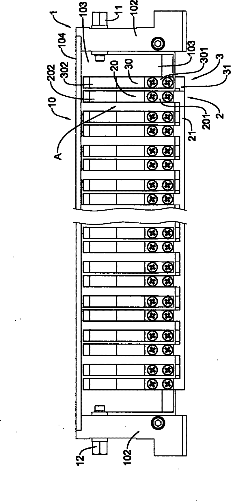
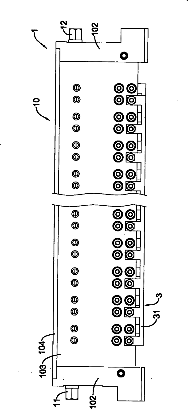
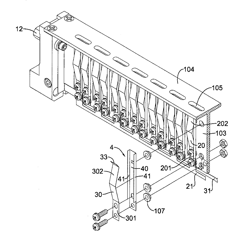
[0060] like Figure 1 to Figure 3 As shown, the preferred embodiment of the capacitor production auxiliary jig of the present invention is disclosed. As shown in the figure, the capacitor production auxiliary jig includes a jig body 1, a first guide pin clamping element 2 and a second guide pin clamping element 3, wherein:

[0061] The jig body 1 mainly includes a carrier 10 and a first conductive terminal 11, or further includes a second conductive terminal 12, and the first conductive terminal 11 and the second conductive terminal 12 are arranged at the same end of the carrier 10 or at different ends. The carrier 10 can be a member made of insulating material or a member made of metal material.

[0062] The first guide pin c...


PUM


Abstract

The invention relates to a jig for assisting electric container production, which is mainly characterized in that a jig body is provided with a first guide pin clamping element and a second guide pin clamping element, wherein the first and the second guide pin clamping elements are respectively provided with a plurality of conductive clamping sheet parts which are paired and arrayed on the jig body, a plurality of electric container semi-finished products or capacitor elements are provided, guide pins of the electric container semi-finished products or capacitor elements are inserted in the electric container semi-finished products or capacitor elements and clamped and positioned by the electric container semi-finished products or capacitor elements, and the jig is used for carrying out the steps of charging formation, chemical liquid filling, polymerization, curing, charging and the like on the capacitor elements and is taken down after the manufacturing steps are completed. The jig disclosed by the invention can be used repeatedly, generates no waste to result in material waste, meets the requirement for environmental protection, and is beneficial to the omission of the steps ofwelding the guide pins on conductive sheets and cutting off the guide pins and the improvement of the convenience and efficiency of the execution of the steps in the manufacturing method.

Description

technical field [0001] The present invention relates to a capacitor manufacturing equipment, in particular to a capacitor production auxiliary jig which is used to assist the charging of an electrolytic capacitor or its capacitor element to be formed or charged, and has the function of being reusable for many times. Background technique [0002] The existing manufacturing process of solid electrolytic capacitors is mainly to wind the anode foil and cathode foil nailed with guide pins together with electrolytic paper to form capacitor elements. Secondly, if Figure 14 As shown, a plurality of capacitor elements 5 are sequentially welded with their long guide pins 50 (connected to the anode foil) on a conductive sheet 51 made of metal, and then these capacitor elements 5 are immersed in the chemical forming liquid of the chemical forming liquid tank 8 , the conductive sheet 51 is connected to the positive pole of the power supply, and the forming solution is connected to the n...

Claims


Application Information

Patent Timeline
Patent Type & Authority Patents(China)
IPC IPC(8): H01G13/00
Inventor 林杰夫
Owner GEMMY ELECTRONICS
Learn More