Flexible thin antenna and manufacturing method thereof

An antenna, thin technology, applied in the direction of the antenna support/installation device, etc., can solve the problems of poor adhesion of the substrate 10, different antenna effects, and increase in resistance value, so as to improve the substantial increase in resistance, improve adhesion, and reduce resistance Effect

Inactive Publication Date: 2011-05-11
PARAGON TECH
View PDF4 Cites 4 Cited by
  • Summary
  • Abstract
  • Description
  • Claims
  • Application Information

AI Technical Summary

Problems solved by technology

[0003] Although both the substrate 10 and the film antenna part 20 have the property of being flexible, due to different materials, the film antenna part 20 is often curled, deformed, or even peeled off from the substrate 10 when subjected to external force or thermal expansion and contraction. In addition, when the film antenna 20 is curled or deformed, the resistance value will increase significantly and the electrical properties will change, which will make the antenna effect different from the expected one.

Method used


Image

  • Flexible thin antenna and manufacturing method thereof
  • Flexible thin antenna and manufacturing method thereof
  • Flexible thin antenna and manufacturing method thereof

Examples


Embodiment Construction

[0016] The implementation of the present invention will be described in more detail below in conjunction with the accompanying drawings, so that those skilled in the art can implement it after studying this specification.

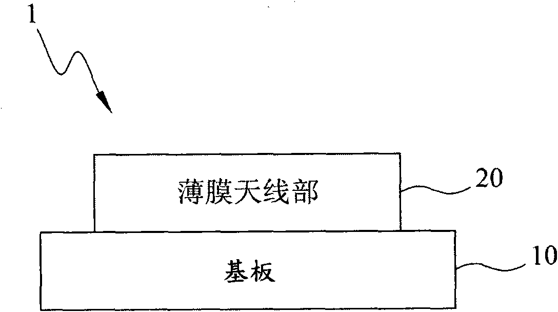
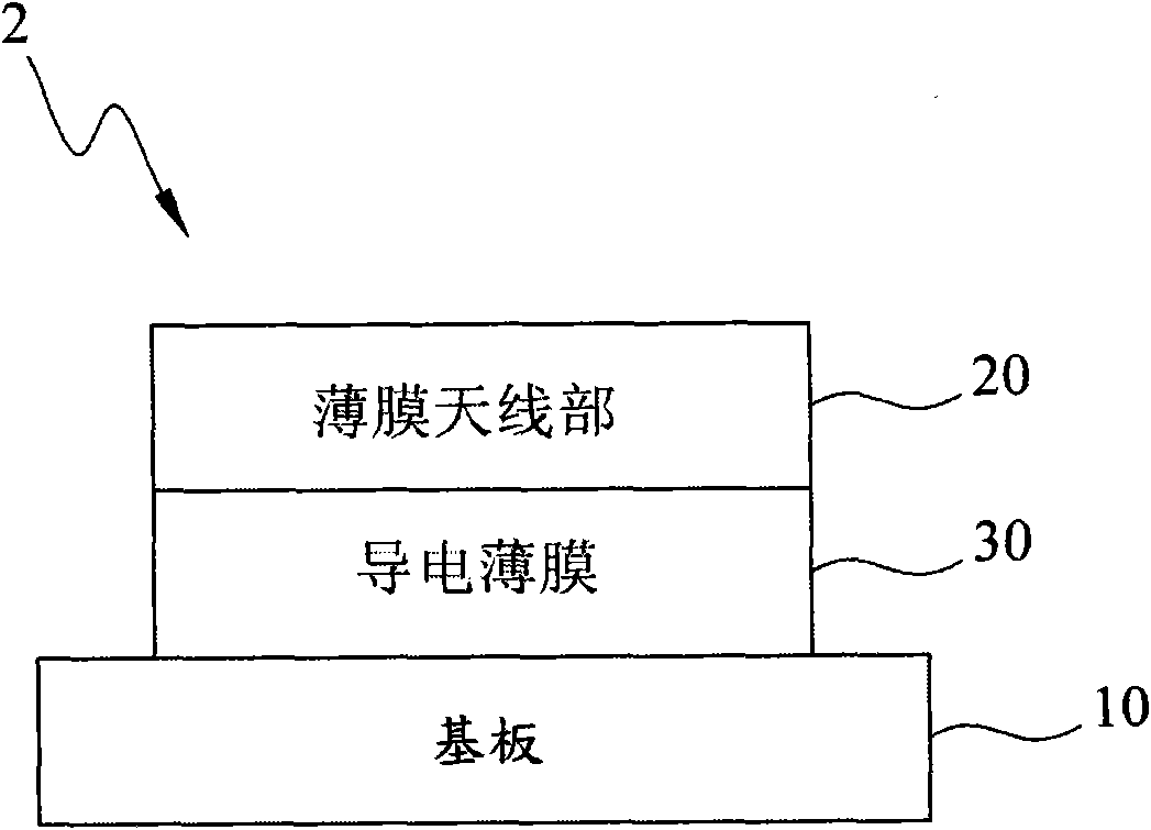
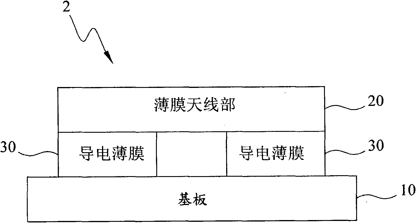
[0017] figure 2 It is a schematic diagram of the first structure of the flexible thin antenna of the present invention. Such as figure 2 As shown, the flexible thin antenna 2 of the present invention includes a substrate 10 , a film antenna part 20 and a conductive film 30 . The substrate 10 is an insulating material, which can be a circuit board, a flexible substrate, an acrylic substrate or other polymer substrates. The film antenna part 20 has an antenna pattern (not shown) and a transceiver component (not shown) for sending and receiving signals, wherein the antenna pattern is a conductive material, such as metal, indium tin oxide (ITO) or aluminum zinc oxide (AZO), etc. . The conductive film 30 is arranged on the substrate 10, and connects the fi...


PUM


Abstract

The invention discloses a flexible thin antenna and a manufacturing method thereof. The flexible thin antenna comprises a base plate, a thin-film antenna part and a thin conducting film, wherein the base plate is made of insulation material; the thin-film antenna part is provided with an antenna pattern and a transmitting / receiving module, and is used for transmitting and receiving signals; and the thin conducting film is arranged on the base plate, is wholly or partially connected with the thin-film antenna part and is flexible. In the invention, mainly the thin conducting film arranged between the base plate and the thin-film antenna part is used for improving the adhesiveness between the base plate and the thin-film antenna part under the action of an external force or expansion and contraction caused by temperature change, lowering the resistance and improving the defect that the resistance of the thin-film antenna part can be greatly increased under the action of an external force. Further, the thin conducting film can lower the resistance, and the thickness of the thin-film antenna part can be reduced, thereby shortening the coating time and simultaneously lowering the manufacturing cost.

Description

technical field [0001] The invention relates to a film antenna and a manufacturing method thereof, in particular to a flexible thin antenna and a manufacturing method thereof. Background technique [0002] refer to figure 1 It is a schematic diagram of a flexible thin antenna in the prior art. In the prior art, the flexible thin antenna 1 includes a substrate 10 and a film antenna portion 20 . The substrate is an insulating material, usually a flexible substrate. The film antenna part has an antenna pattern and a transceiver component for sending and receiving signals, wherein the antenna pattern is made of metal material. [0003] Although both the substrate 10 and the film antenna part 20 have the property of being flexible, due to different materials, the film antenna part 20 is often curled, deformed, or even peeled off from the substrate 10 when subjected to external force or thermal expansion and contraction. In addition, when the film antenna 20 is warped or defor...

Claims


Application Information

Patent Timeline
Patent Type & Authority Applications(China)
IPC IPC(8): H01Q1/14
Inventor 张源利许志和
Owner PARAGON TECH
Why Eureka
Try Eureka