Tire manufacturing method and apparatus

A manufacturing method and tire technology, which can be applied to auxiliary devices for rope making, tire parts, transportation and packaging, etc., can solve the problems of uneven amplitude and wavelength of corrugated steel cords, and can not fully improve the durability of the bead portion, etc. To achieve the effect of simple winding control, uniform amplitude, and improved performance

Inactive Publication Date: 2011-05-11
BRIDGESTONE CORP
View PDF6 Cites 9 Cited by
  • Summary
  • Abstract
  • Description
  • Claims
  • Application Information

AI Technical Summary

Problems solved by technology

Therefore, the amplitude and wavelength of the corrugated steel cords become very non-uniform throughout the cord reinforcing layer, especially when viewed in the radial direction, resulting in a problem that the durability of the bead portion cannot be sufficiently improved.

Method used


Image

  • Tire manufacturing method and apparatus
  • Tire manufacturing method and apparatus
  • Tire manufacturing method and apparatus

Examples


no. 1 approach

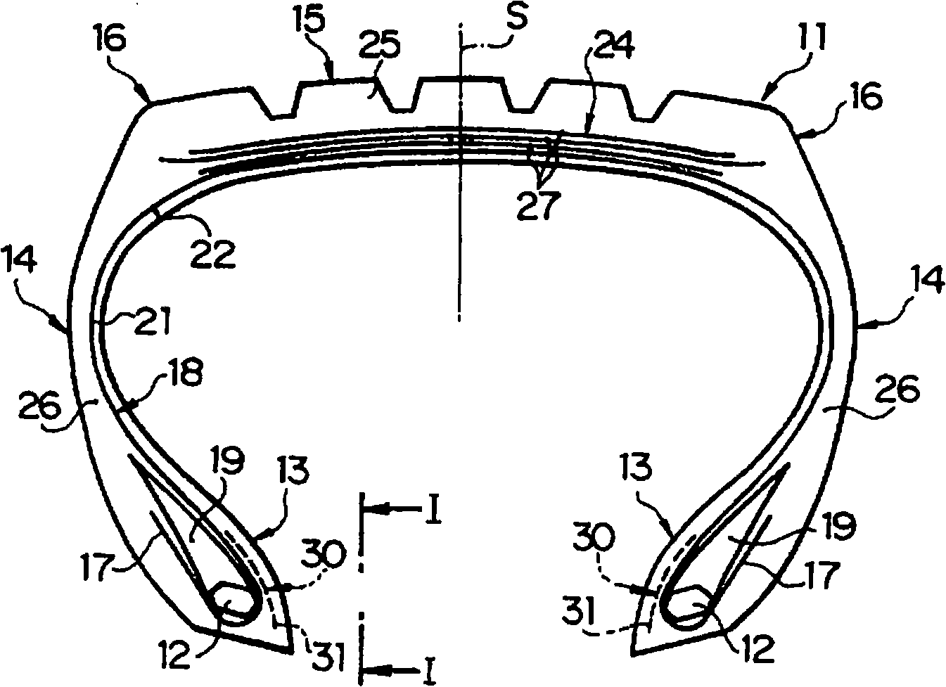
[0028] exist figure 1 and figure 2 In , reference numeral 11 denotes a vulcanized pneumatic radial tire that can be used for, for example, trucks, buses, and the like. The pneumatic radial tire 11 is provided with a pair of bead portions 13 in which a bead core 12 is embedded, and a pair of sidewall portions 14 respectively extending radially outward from the bead portions 13 . Reference numeral 15 denotes a substantially cylindrical tread portion. A pair of shoulder portions 16 is located between each axial end of the tread portion 15 and the radially outer end of each side wall portion 14 .

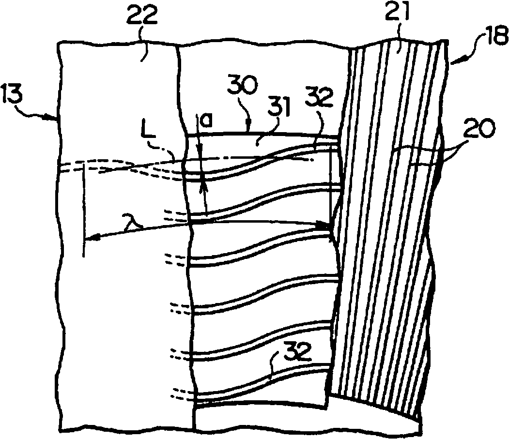
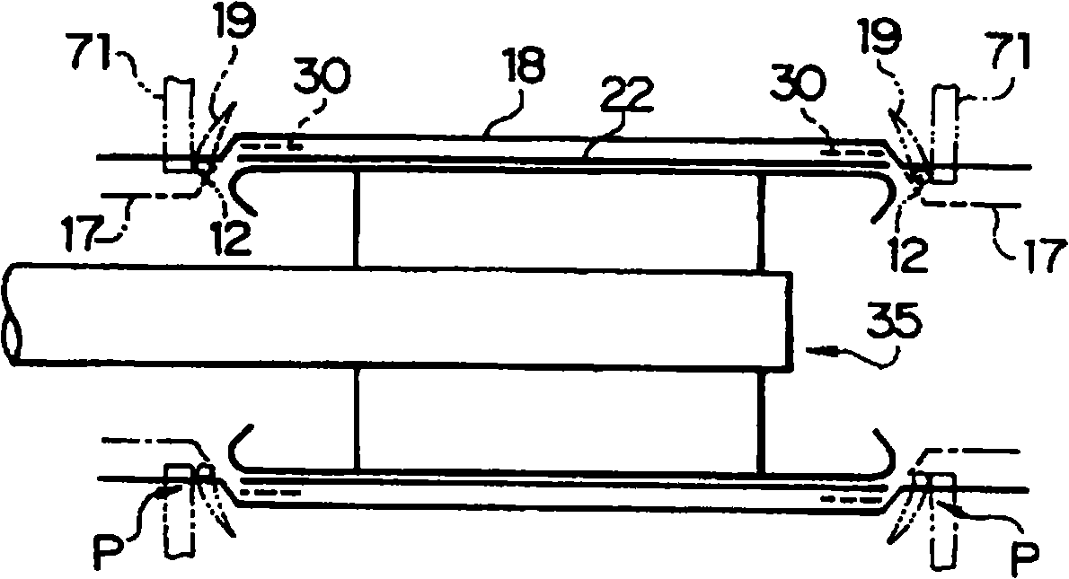
[0029] The pneumatic tire 11 also has a carcass layer 18 annularly extending between a pair of bead cores 12 to reinforce the sidewall portion 14 and the tread portion 15 . The two ends of the carcass layer 18 are folded around the bead core 12 and the filler 19, and the radial inner ends of the filler 19 are fixed by the bead core 12, thereby, the two ends of the carcass layer 18 ...


PUM


Abstract

A cord reinforcing layer (30) can be molded at high efficiency while being easily controlled, and the amplitude or wavelength of wave-shaped steel cords (32) can be made uniform over the entire cord reinforcing layer (30). When multiple wave-shaped steel cords (32) (ribbon-like body (37)) are wound on a cylindrical molding drum (35) to mold the cylindrical cord reinforcing layer (30), since the amount of elongation is reduced moving away, in the axial direction, from a set position P for a bead core (12), the amount of elongation provided in advance for the wave-shaped steel cords (32) near the set position P approaches the amount of elongation based on swelling deformation of the wave-shaped steel cords (32) at a position away from the set position P. In this way, the amplitude and / or the wavelength of the wave-shaped steel cords in the tire can be made uniform over the entire cord reinforcing layer (30).

Description

technical field [0001] The present invention relates to a manufacturing method and manufacturing apparatus of a tire in which a cord reinforcing layer formed of corrugated steel cords is provided between a bead portion and a shoulder portion. Background technique [0002] As a conventional tire, there is known, for example, as described in Japanese Patent Application Laid-Open No. 2006-160053, in which a cord reinforcing layer overlapping a folded portion of a carcass layer is partially provided between a bead portion and a shoulder portion (wire chafer) to prevent peeling at the end of the folded portion of the carcass layer, thereby improving the durability of the bead portion. [0003] Such a cord reinforcement layer is formed in such a manner that a single rubber-coated steel cord is bent in a wave form with approximately constant amplitude and wavelength, and then helically wound directly around a toroidal carcass layer. Axial outside of the fold. However, in the case...

Claims


Application Information

Patent Timeline
Patent Type & Authority Applications(China)
IPC IPC(8): B29D30/30B60C15/06D07B1/06
CPCB29D30/3028B29D30/44B60C15/06D07B1/0646D07B7/025D07B2201/2021D07B2501/2046
Inventor 小川裕一郎
Owner BRIDGESTONE CORP
Why Eureka
Try Eureka