Check patentability & draft patents in minutes with Patsnap Eureka AI!

Load circuit overcurrent protection device

A technology of protection device and load circuit, applied in the direction of output power conversion device, circuit, electronic switch, etc., can solve the problems of affecting the overcurrent judgment value Iovc, unable to cut off the circuit, etc.

Inactive Publication Date: 2011-05-11
YAZAKI CORP
View PDF7 Cites 2 Cited by
  • Summary
  • Abstract
  • Description
  • Claims
  • Application Information

AI Technical Summary

Problems solved by technology

[0027] As described above, the overcurrent protection device of the load circuit of the prior art has the problem that when there is a deviation ±ΔRon in the on-resistance Ron of the semiconductor element (MOSFET), the deviation affects the overcurrent judgment value Iovc, and thus cannot Cut off the circuit based on the accurate overcurrent judgment value Iovc

Method used


Image

  • Load circuit overcurrent protection device
  • Load circuit overcurrent protection device
  • Load circuit overcurrent protection device

Examples


Embodiment Construction

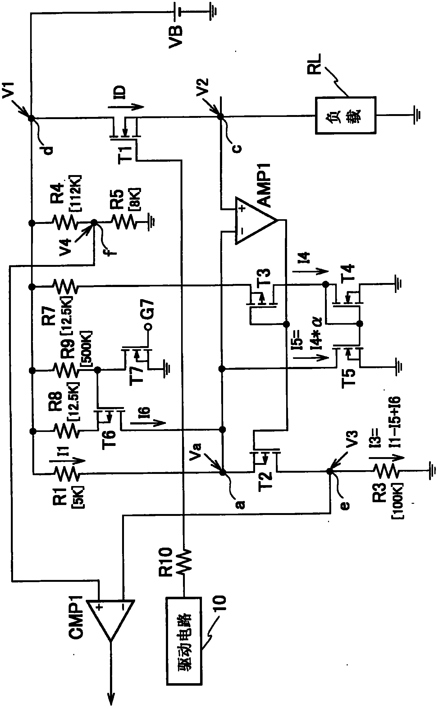
[0107] Hereinafter, embodiments according to the present invention will be described with reference to the drawings. figure 1 is a circuit diagram showing an overcurrent protection device and a load circuit according to a first embodiment of the present invention. Such as figure 1 As shown, the load circuit includes a series circuit formed of a battery VB, a MOSFET ( T1 ) as a semiconductor element, and a load RL such as a lamp or a motor. The gate (control electrode) of MOSFET (T1) is connected to the drive circuit 10 via the resistor R10. Thus, the MOSFET ( T1 ) is turned on and off in response to the drive signal output from the drive circuit 10 , thereby switching the load RL between the drive state and the stop state.

[0108] The drain (first main electrode) of the MOSFET ( T1 ) (point d: voltage V1 ) is grounded via a series circuit of resistors R4 (eg, 112 [KΩ]) and R5 (eg, 8 [KΩ]). In addition, the point d is grounded via a series circuit of the resistor R1 (for ...


PUM


Abstract

An overcurrent protection apparatus for a load circuit can detect an overcurrent with a high accuracy without being influenced by a deviation +-[Delta]Ron of the on-resistance of a semiconductor element (T1). Supposing that a ratio (R3 / R1) between a resistor R3 and a resistor R1 is an amplification factor m, a determination voltage generated by resistors R4, R5 is V4 and the average value of the on-resistance of a MOSFET (T1) is Ron, the overcurrent protection apparatus for a load circuit controls either a current I3 flowing through the resistor R3 or a current IR5 flowing through the resister R5 so that the output signal of a compactor CMP1 is inverted when a current having a value of (V4 / m / Ron) flows into the MOSFET (T1). For example, when the deviation +-[Delta]Ron of the on-resistance has a positive value, either the current I3 is generated by subtracting a current proportional to the deviation +-[Delta]Ron from a current I1 flowing through the R1 or the current IR5 is generated by adding a current proportional to the deviation +-[Delta]Ron to a current IR4 flowing through R4. In contrast, when the deviation +-[Delta]Ron of the on-resistance has a negative value, either the current I3 is generated by adding the current [Delta]I1 proportional to the deviation +-[Delta]Ron to the current I1 or the current IR5 is generated by subtracting the current proportional to the deviation +-[Delta]Ron from the current IR4.

Description

technical field [0001] The present invention relates to an overcurrent protection device which detects an overcurrent and protects the load circuit when the overcurrent flows through the load circuit, and in particular, relates to a method for avoiding deviation due to on-resistance of semiconductor elements (change) and cause a drop in detection accuracy. Background technique [0002] For example, loads such as various lamps, motors, etc. mounted on vehicles are connected to batteries (power sources) via semiconductor elements so that the operations of the loads are individually controlled by switching on / off states of the corresponding semiconductor elements. Due to failure or malfunction of the load circuit or various circuits connected to the load circuit, an overcurrent may flow into the load circuit constituted by the battery, the semiconductor element, and the load. When an overcurrent flows, the semiconductor element is overheated, and the wiring harness connected b...

Claims


Application Information

Patent Timeline
Patent Type & Authority Applications(China)
IPC IPC(8): H03K17/08H02M1/00H03K17/687
CPCH03K17/0822H03K2217/0027
Inventor 大岛俊藏
Owner YAZAKI CORP
Features
  • R&D
  • Intellectual Property
  • Life Sciences
  • Materials
  • Tech Scout
  • Unparalleled Data Quality
  • Higher Quality Content
  • 60% Fewer Hallucinations
Learn More