
Carried-on-back lightweight combine harvester

A combine harvester and back-carrying technology, applied in the direction of harvesters, cutters, agricultural machinery and implements, etc., can solve the problems of difficult field transfer, low harvesting efficiency, high labor intensity, etc., to simplify the complex transmission system, reduce the Labor intensity and the effect of reducing harvesting costs

Inactive Publication Date: 2011-05-18
戴文育
View PDF3 Cites 3 Cited by
  • Summary
  • Abstract
  • Description
  • Claims
  • Application Information

AI Technical Summary

Problems solved by technology

[0002] The existing harvesters are all large and medium-sized highly mechanized production equipment, which have the outstanding advantages of saving manpower and high work efficiency, and are suitable for large-scale harvesting operations in the large farmland area of ​​Pingba area; however, in Feipingba Areas, especially hills and mountainous areas with small and scattered slopes, water and dry farmland plots with uneven terrain and poor road conditions, limited by terrain, planting area, and economic factors, large and medium-sized highly mechanized productivity loses its role; In such areas, farmland harvesting has to be carried out manually with a sickle, which is labor-intensive and the harvesting efficiency is low.
The currently used small rice and wheat harvesters, some small harvesters, have relatively complicated mechanisms, and their own volume is still large and heavy. It is especially difficult to transfer in the field. Some road conditions and terrain requirements also limit the use of harvesters, or they cannot be used, or Inflexible to use etc.

Method used


Image

  • Carried-on-back lightweight combine harvester
  • Carried-on-back lightweight combine harvester
  • Carried-on-back lightweight combine harvester

Examples


Embodiment Construction

[0028] The following combination Figure 1 to Figure 9 The mechanism and structural arrangement of the embodiment of the present invention are described in detail.

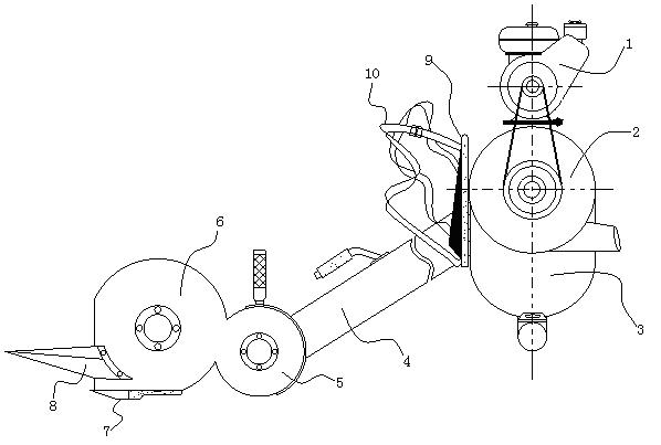
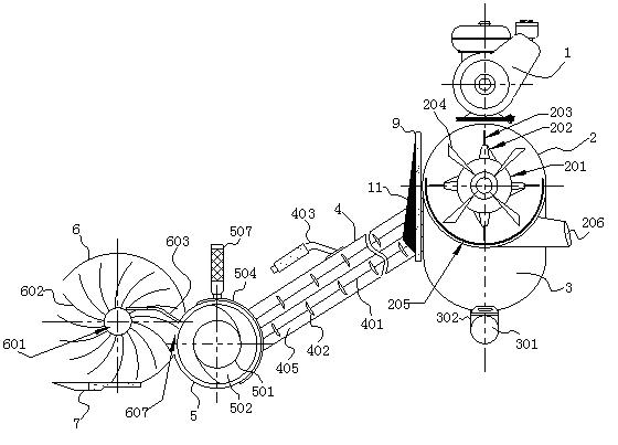
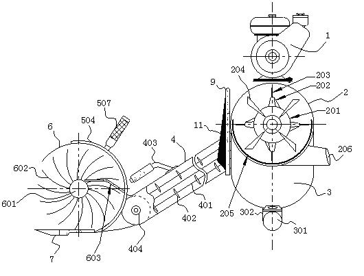
[0029] As a preferred solution of the present invention, a lightweight carry-on combine harvester roughly mainly includes components that are connected by the engine (1) power source output shaft and the threshing drum (2), and the lower end of the threshing drum (2) is arranged for threshing The storage bin (3), on the outside of the barrel wall of the threshing drum (2) and the shell of the threshing storage bin (3), also includes a back plate (9), a back pad (11), and a strap (10), One end of the threshing drum (2) is connected to the conveying device (4), and the conveying device (4) is directly connected to the reeling device (6), or you can choose to add a screw auger device (5), and bordering to the reeling device ﹙6﹚, the main cutter﹙7﹚ is arranged at the front end of the reeling device﹙6﹚, or a pair of cutt...


PUM


Abstract

The invention relates to the field of agricultural machinery, and discloses a carried-on-back lightweight combine harvester, which mainly comprises a power source output shaft of an engine and a threshing roller. A threshing storage bunker is arranged at the lower end of the threshing roller. A back plate, a back cushion and back straps are arranged outside the roller wall of the threshing roller and a shell of the threshing storage bunker. The carried-on-back lightweight combine harvester is characterized in that: one end of the threshing roller is connected with a conveyance device; the conveyance device is directly connected with a corn snapping device, or is selectively provided with a spiral auger device and then connected to the corn snapping device; a main sickle is arranged at the front end of the corn snapping device, or a secondary sickle can be selectively connected to the front end of the corn snapping device; and nearside dividers are arranged on the roller shell at the two ends of the corn snapping device respectively. Compared with the prior art, the carried-on-back lightweight combine harvester has the advantages and aims of simplifying a conventional complex drive system by an optimal combination, making simple the structure and greatly reducing the dead weight.

Description

Technical field [0001] The invention relates to the field of agricultural machinery. It is a combine harvester for harvesting rice, wheat and other crops. Specifically, it can be carried on the back of laborers, and can be used for combined harvesting while walking in the crop field. The harvester, specifically, is a lightweight and portable combine harvester. Background technique [0002] The existing harvesters are all large and medium-sized highly mechanized production equipment, which have outstanding advantages of saving manpower and high work efficiency, and are suitable for large-scale harvesting operations in the large farmland of Pingba area; however, in non-pingba area Areas, especially hills and mountainous areas, are small and scattered. Irrigated and dry farmland plots are uneven and road conditions are poor. Limited by topography, planting area, and economic factors, the productivity of large and medium-sized highly mechanized areas has lost its effect; In such are...

Claims


Application Information

Patent Timeline
IPC IPC(8): A01D41/00A01D41/12A01D57/00A01D57/02A01D34/404A01F7/02A01F12/18
Inventor 戴文育
Owner 戴文育
Learn More