Method for manufacturing helical blade

A technology of a helical blade and a manufacturing method, which is applied to the manufacturing field of the helical blade, can solve the problems of cumbersome operation, low production efficiency, unable to form a positive helical surface, etc., and achieves the effect of improving work efficiency, avoiding cross operation and good forming effect.

Active Publication Date: 2011-05-18
太仓市宝马油脂设备有限公司
View PDF3 Cites 5 Cited by
  • Summary
  • Abstract
  • Description
  • Claims
  • Application Information

AI Technical Summary

Problems solved by technology

[0006] (2) The inner hole of the first blade at both ends of the spiral blades A and B does not fit well with the mandrel
However, the blades at the two ends of the spiral blades A and B are subjected to a large force during the cold drawing process, and the deformation is also large, and cannot form a positive helical surface, so the inner holes of the blades at the two ends of A and B are not very close to the spindle Good fit with curved gaps
[0008] (3) The blade at the B end of the spiral blade is easily damaged
[0010] (4) After welding, the welding deformation produced is large
[0011] Spiral blades are generally made of thin plate materials by welding. After welding, the pressure caused by the longitudinal shrinkage of the weld will cause the blade to lose stability and produce wavy deformation. After the spiral blade produces wavy deformation, it will affect the screw conveying. The process effect of the machine
[0012] In addition, since the helical blades are free-formed, in addition to the inaccurate pitch of the helical blades, the operation is cumbersome, the production efficiency is low, and the labor load is large (two operators must cooperate with the operation, one person controls the force P exerted by the wire rope, and the other person at any time) Correct the spiral blade) and other deficiencies

Method used


Image

  • Method for manufacturing helical blade
  • Method for manufacturing helical blade
  • Method for manufacturing helical blade

Examples


Embodiment Construction

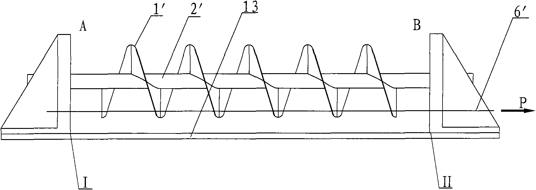
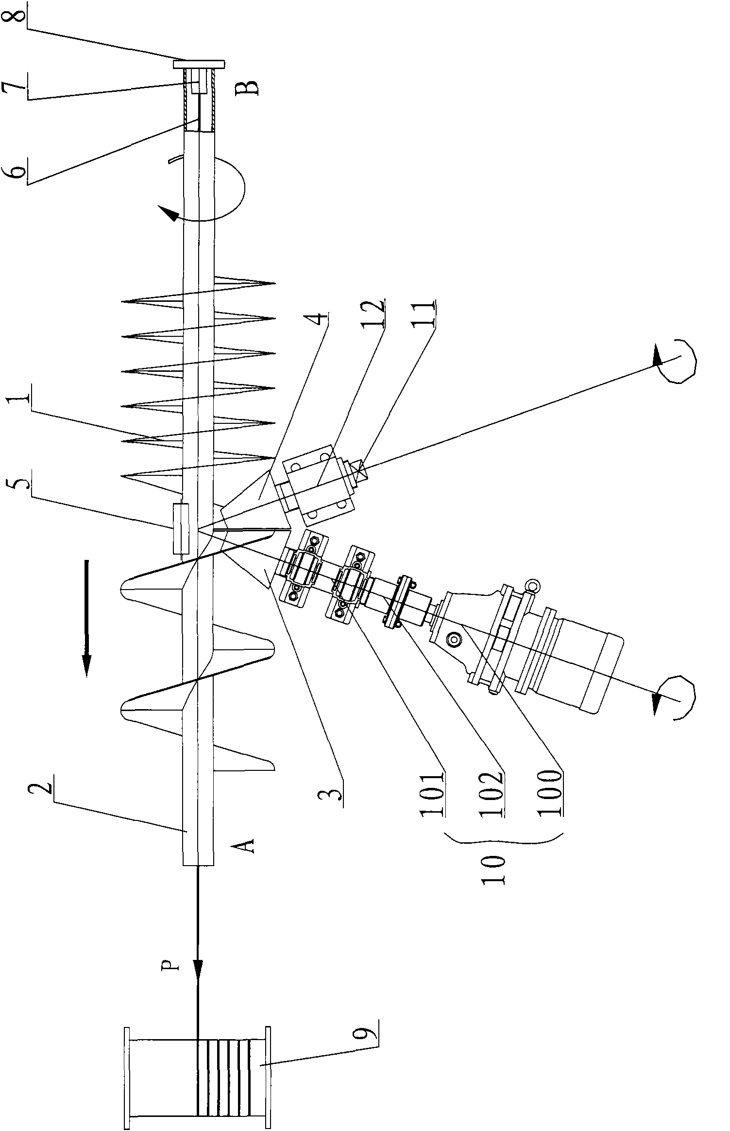
[0032] Such as image 3 As shown, the manufacturing process of the spiral blade according to the present embodiment is as follows:

[0033] (1) Determine the position of the integral blade 1 and the mandrel 2: string the welded integral blade 1 with the inner hole on the mandrel 2, adjust the driving tapered roller 3 and the driven tapered roller 4, so that the two rollers clamp the whole At the starting end A end of the blade 1, the active tapered roller 3 can only rotate but cannot expand and contract in the axial direction. The driven tapered roller 4 can rotate under the drive of the driving tapered roller 3 . The driven tapered roller 4 is connected on a screw shaft 11 by a sliding bush, and the screw shaft 11 is threadedly connected with the fixing seat 12, so that the driven tapered roller 4 can rotate, the screw shaft 11 does not move, and the screw shaft 11 can only Axially moving along itself is realized by adjusting the tail end with a wrench, so that the driven t...


PUM


Abstract

The invention relates to a method for manufacturing a helical blade, comprising the following steps of: (1) stringing an overall blade on a mandrel, clamping a starting end of the overall blade through a driving conical roller and a driven conical roller capable of rotating around a shaft axis per se, and resisting the mandrel by utilizing a blocking roller capable of autorotating; (2) penetrating through the mandrel by utilizing a steel wire rope, connecting the B end of the mandrel to a universal joint, connecting the A end to a windlass, and linking the windlass and the driving conical roller; and (3) starting a driving device of the driving conical roller, stopping the driving device when the overall blade extends out 3-5 cm, firstly welding an inner diameter of the A end of the overall blade and the mandrel, fixing the overall blade, then restarting, temporarily stopping the driving device after the overall blade extends out a section again, welding the inner diameter of the overall blade and the mandrel, restarting the driving device, and repeating the operations in turn to obtain the helical blade. The method for manufacturing the helical blade has high working efficiency and favorable safety; and the obtained helical blade has accurate and uniform screw pitch and favorable quality.

Description

technical field [0001] The invention relates to a manufacturing method of a spiral blade. Background technique [0002] Screw conveyor (commonly known as auger) has been widely used in many industries. The screw blade is the main working part of the screw conveyor. Using reasonable technology to produce high-quality screw blades can not only improve the use of screw blades It is also of great significance to increase the life of the screw conveyor, improve the productivity of manufacturing the screw blade, and to better utilize the process effect of the screw conveyor. At present, there are many methods for manufacturing spiral blades, and the overall cold drawing method is widely used. This method is simple to produce and low in cost, but it also has many disadvantages. [0003] Such as figure 1 and 2 shown. The overall cold drawing process is as follows: the welded overall blade (1') is strung on the mandrel (2') with the inner hole, and the mandrel (2') is installed o...

Claims


Application Information

Patent Timeline
Patent Type & Authority Applications(China)
IPC IPC(8): B23K31/02
Inventor 马志强曾凡中叶志刚徐晓红王健
Owner 太仓市宝马油脂设备有限公司
Why Eureka
Try Eureka