
Solid solution heat treatment furnace

A technology of solution heat treatment and heat treatment furnace, applied in the direction of heat treatment equipment, furnace, furnace type, etc., can solve the problems of increasing equipment cost, energy waste, low thermal efficiency, etc., and achieve the effect of reducing heat loss, ensuring thermal efficiency, and reducing thermal conductivity

Active Publication Date: 2012-10-03
MCC CAPITAL ENGINEERING & RESEARCH +1
View PDF1 Cites 0 Cited by
  • Summary
  • Abstract
  • Description
  • Claims
  • Application Information

AI Technical Summary

Problems solved by technology

[0005] 1. No cooling furnace roll, its structure is simple and easy to install, but when the furnace temperature is higher than 1200 degrees Celsius, the material of the roll body of the non-cooling furnace roll must have extremely high high-temperature strength performance, and it is bound to use alloys with high Cr and Ni content Hot steel, resulting in extremely high cost of furnace rollers, greatly increasing equipment costs
[0006] 2. The direct cooling furnace roller device, due to the direct contact between the cooling medium and the inner wall of the roller body, the surface temperature of the roller body is very low, the heat loss of the heat treatment furnace is large, the thermal efficiency is low, and the energy waste is more serious; moreover, the heated workpiece is reduced heat treatment quality
[0007] At this temperature, the furnace roller sealing structure of the conventional roller hearth heat treatment furnace can no longer meet the sealing and heat insulation requirements at this high temperature, and the conventional quenching machine cannot meet the cooling requirements of the workpiece at this high temperature.

Method used


Image

  • Solid solution heat treatment furnace
  • Solid solution heat treatment furnace
  • Solid solution heat treatment furnace

Examples


Embodiment approach 1

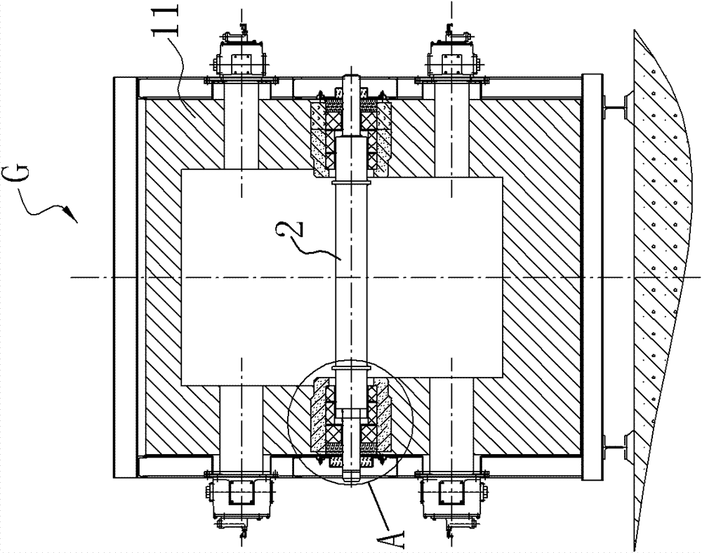
[0027] Please refer to figure 1 and figure 2 As shown, the solid solution heat treatment furnace according to the embodiment of the present invention includes a roller hearth heat treatment furnace G and a quenching machine 6 connected to each other. The roller hearth heat treatment furnace G includes a furnace body 1 and a plurality of furnace roller devices 2. Furnace walls 11 are arranged around the furnace body 1, and furnace body feeders are respectively arranged on opposite sides of the furnace body 1. Port and furnace body discharge port; a plurality of furnace roller devices 2 are arranged in parallel between the furnace body feed port and the furnace body discharge port, and the two ends of each furnace roller device 2 are sealed and arranged on the furnace body through the sealing module 3 In the wall 11, each furnace roller device 2 includes a water-cooled support shaft 21 and a roll body 22, and the water-cooled support shaft 21 is provided with a cooling water c...

Embodiment approach 2

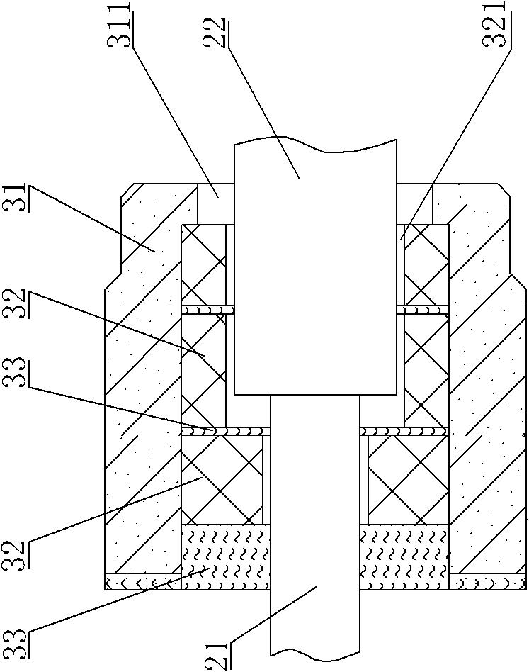
[0043] see figure 2 and Figure 4 As shown, the embodiment of the invention relates to a sealing module 3 .

[0044] The sealing module 3 includes a sealing brick 31, the sealing brick 31 has a through hole 311, and a multi-layer fiber module 32 is arranged in the axial direction in the through hole 311, and the end of the furnace roller device 2 is pierced through the In the multi-layer fiber module 32, a fiber blanket 33 is provided at the end of the furnace roller device 2 passing through the sealing brick 31, and the fiber blanket 33 is sealed between the sealing brick 31 and the furnace roller. between the ends of the device.

[0045] Specifically, the inner opening of the sealing brick 31 is in the shape of a cylinder, and it is fixedly arranged in the furnace wall 11 of the roller hearth heat treatment furnace G. The through hole 311 is provided at the center of the sealing brick 31, and the end of the furnace roller device 2 penetrates into the through hole 311 of ...

Embodiment approach 3

[0054] see Figure 5 to Figure 7A As shown, the embodiment of the invention relates to a quenching machine 6 .

[0055] see Figure 6 and Figure 7 As shown, the quenching machine of the embodiment of the present invention includes a casing 61, and the two sides of the casing are respectively provided with a material inlet and a material outlet correspondingly, and a plurality of parallel Quenching roller table 62, the two shaft ends of each quenching roller table 62 are respectively connected on the casing 61, there are at least two cooling sections along the arrangement direction of the roller table in the casing 61, the first cooling section L1 is water-cooled and The air-cooled cooling section, the second cooling section L2 is a water-cooled cooling section; the bottom of the casing 61 is provided with a drainage system 63 , and the drainage system 63 is located below the roller table 1 .

[0056] It is suitable for stainless steel or heat-resistant alloy steel and othe...


PUM


Abstract

The invention discloses a solid solution heat treatment furnace which comprises a roller hearth type heat treatment furnace and a quenching machine which are connected, wherein the roller hearth type heat treatment furnace comprises a furnace body, furnace walls are arranged at the periphery of the furnace body, a furnace body feed hole and a furnace body discharge hole are respectively and correspondingly arranged in the furnace body, a plurality of furnace roller devices are arranged in parallel between the furnace body feed hole and the furnace body discharge hole, both ends of each furnace roller device are sealed in the furnace walls through a sealing module, each furnace roller device comprises a water cooling support shaft and a roller body, each water cooling support shaft is provided with a cooled water channel, each roller body is provided with an axially perforating cavity, each water cooling support shaft passes through the cavity and penetrates in the roller body, the roller body synchronously rotates with each water cooling support shaft, a containing space is arranged between the outer wall of each water cooling support shaft and the inner wall of each roller body, a plurality of support assemblies are arranged in parallel in the containing space at intervals along the axial direction, one side of each support assembly is connected with the outer wall of each water cooling support shaft, and a predetermined gap is arranged between the other side of each support assembly and the inner wall of each roller body.

Description

technical field [0001] The invention relates to a solution heat treatment furnace, in particular to a solution heat treatment furnace for high-temperature stainless steel and heat-resistant alloy steel, which can operate stably for a long time under the condition that the furnace temperature is higher than 1250°C. Background technique [0002] The solution heat treatment furnace includes an interconnected roller hearth heat treatment furnace and a quenching machine. The roller hearth heat treatment furnace is a process equipment commonly used in iron and steel metallurgy, nonferrous metallurgy and machinery industries. During the production process of the roller hearth heat treatment furnace, the furnace roller is placed inside the heating furnace, and the heated workpiece is placed on the furnace roller. According to the speed and temperature set by the relevant process, the workpiece is driven by the furnace roller and heated while being transported in the heating furnace....

Claims


Application Information

Patent Timeline
Patent Type & Authority Patents(China)
IPC IPC(8): C21D1/78C21D1/62F27B9/24B65G39/02
Inventor 杨三堂胡文超戴志刚张刚
Owner MCC CAPITAL ENGINEERING & RESEARCH
Learn More