Construction method for imitated frame structure of long-span prestressed concrete beam slab

A concrete beam and frame structure technology, which is applied to truss structures, girders, formwork/formwork/work frames, etc., can solve the problems of increased labor and materials, large cross-section of frame beams, and difficult construction sequence of beams and slabs. easy effect

Inactive Publication Date: 2011-05-18
柳忠林
View PDF3 Cites 9 Cited by
  • Summary
  • Abstract
  • Description
  • Claims
  • Application Information

AI Technical Summary

Problems solved by technology

However, there is a provision in the literature that the use of hinged frame structures is not allowed in earthquake fortified areas.
The second is to design the frame structure beams of such long-span members according to the principles of traditional frame structures (this is the only option that can meet the requirements of engineering drawing review according to the design requirements required by the code), but the consequences are not only the cross-section of the frame beams Large and heavy, not only affect the appearance of the building, use space, greatly increase the labor and materials, but also make the construction difficult
Because the beam must be constructed on site, it is difficult to reasonably match the construction sequence of the beam and slab, thus prolonging the construction period

Method used


Image

  • Construction method for imitated frame structure of long-span prestressed concrete beam slab
  • Construction method for imitated frame structure of long-span prestressed concrete beam slab
  • Construction method for imitated frame structure of long-span prestressed concrete beam slab

Examples


Embodiment Construction

[0021] The present invention will be described in detail below in conjunction with the accompanying drawings and embodiments.

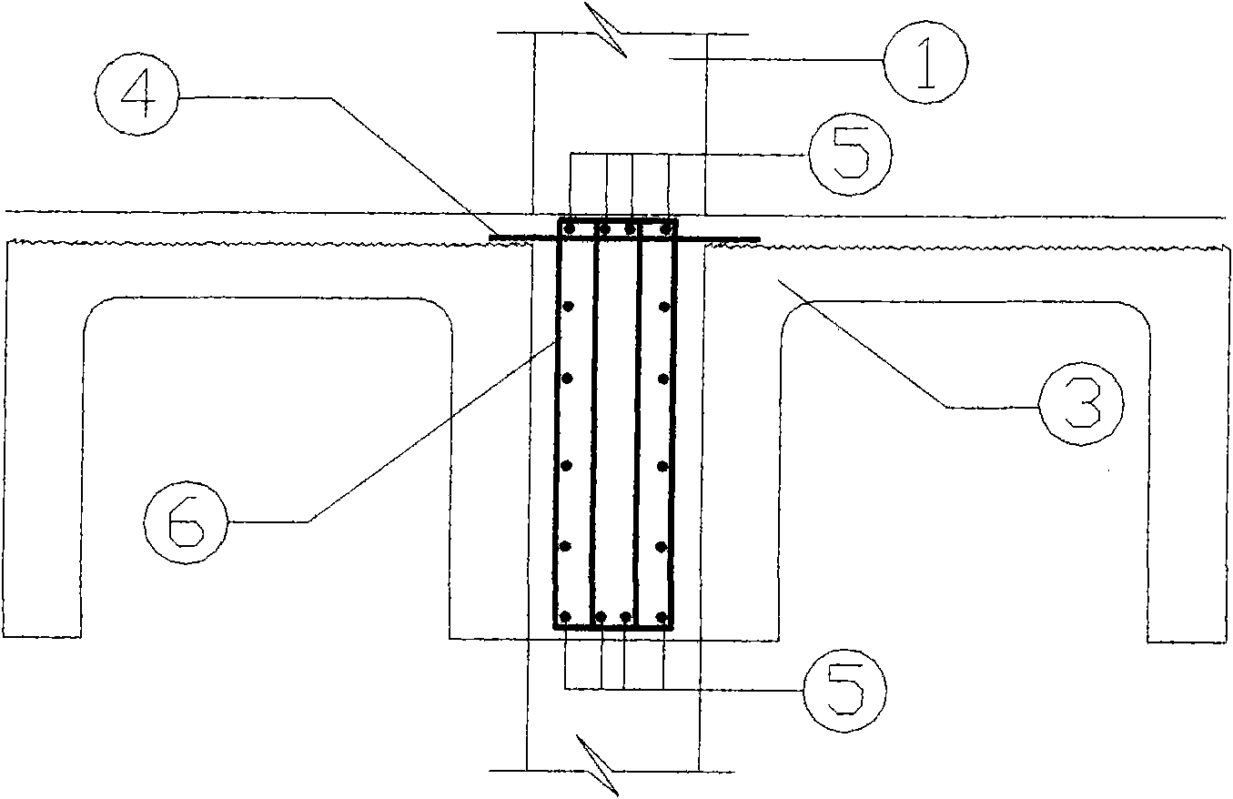
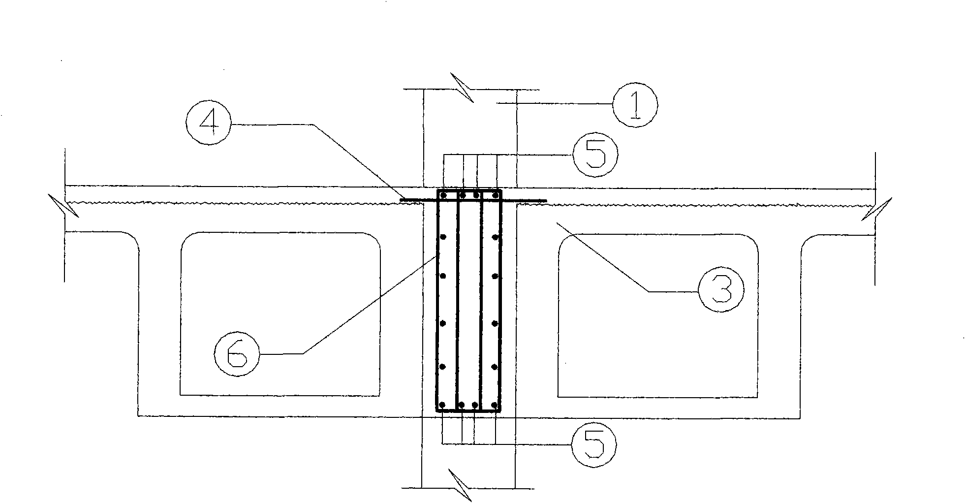
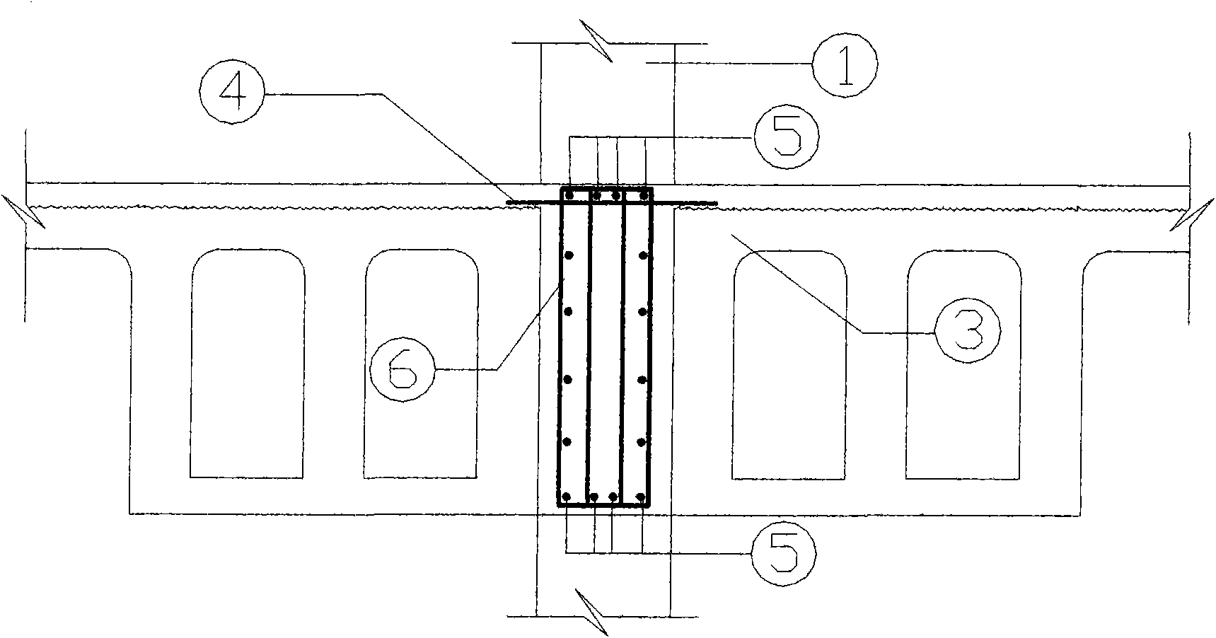
[0022] Such as Figure 5 As shown in the flow chart, the frame columns and frame stringers are first installed using the conventional process. After the frame columns and frame stringers are installed, a large-span prestressed bridge with no flange or no partial flange on one side is installed on both sides of the frame column. The concrete beam slab forms the side formwork of the beam, and the suspended beam bottom formwork is erected along the side formwork, and the steel bars (non-prestressed steel bars) of the beam are arranged slightly upward in the space formed by the bottom formwork, including the connection between the vertical steel bars on the top of the slab and the frame column steel bars longitudinal ribs and stirrups. Use EPS board to fill the part outside the concrete protective layer inside the steel bar in the beam, and then pour the...


PUM


Abstract

The invention relates to a construction method for an imitated frame structure of a long-span prestressed concrete beam slab, belonging to the technical field of constructional engineering structures. The method comprises the following steps of: installing single T-shaped slabs consisting of prestressed hollow single T-shape beam slabs with no flanges or flanges removed, or a plurality of T-shaped box-shaped beams, or trough slabs or rectangular beams at two sides close to a frame column after the frame column and a frame longitudinal beam are installed; arranging transverse constructed erected reinforcing steel bars on the frame column; suspending a bottom template on the deck or erected reinforcing steel bars along a beam slab arris or a side direction; leveling the bottom template with the bottom of the prestressed concrete beam slab; arranging reinforcing steel bars of the beam in a space formed by the template; connecting the reinforcing steel bars with the reinforcing steel bars of the frame column; then connecting the reinforcing steel bars again by hooping; and finally, pouring and tamping concrete as required to form a frame beam, i.e. an imitated frame beam. The method disclosed by the invention has the advantages of reducing the section of the imitated frame beam, not needing to cut off the flanges of the T-shaped slab, lowering the cost and improving construction and precasting benefits.

Description

technical field [0001] The invention belongs to the technical field of construction engineering structures, and in particular relates to a construction method for a large-span prestressed concrete beam-slab quasi-frame structure. Background technique [0002] Among the long-span prestressed concrete beams and slabs, multi-T box girders, channel slabs, single T beams and slabs with hollow single T beams and slabs (hereinafter referred to as T-slabs) and rectangular beams were used earlier abroad. Its biggest advantage is: large span, large column spacing and large span structure can be built; low sagittal height (0.45 ~ 1.085m, about 1 / 3 ~ 1 / 4 of the height of the roof truss structure <roof truss height plus roof panel height>), it can Significantly reduce the height of the building to achieve material and energy saving; good stability, no need for additional lateral support; large component coverage, high installation efficiency, after the installation of the board, th...

Claims


Application Information

Patent Timeline
Patent Type & Authority Applications(China)
IPC IPC(8): E04B5/43E04C3/26E04G11/42E04G21/00
Inventor 柳忠林
Owner 柳忠林
Why Eureka
Try Eureka