Miniature diaphragm valve

A diaphragm valve and valve body technology, applied in the direction of diaphragm valves, diaphragms, valve details, etc., can solve the problems of high manufacturing precision requirements, narrow application range, and difficult manufacturing process to meet the requirements, so as to reduce processing accuracy requirements and improve pressure resistance Ability, the effect of improving the performance of fluid pressure resistance

Inactive Publication Date: 2013-04-10
东莞市青野电子科技有限公司
View PDF1 Cites 0 Cited by
  • Summary
  • Abstract
  • Description
  • Claims
  • Application Information

AI Technical Summary

Problems solved by technology

[0003] At present, various similar valves have high manufacturing precision requirements, and the general manufacturing process is difficult to meet the requirements; there are certain defects in their pressure range, sealing, internal volume, flow capacity, response time, etc., and the scope of application is relatively narrow.

Method used


Image

  • Miniature diaphragm valve
  • Miniature diaphragm valve

Examples


Embodiment Construction

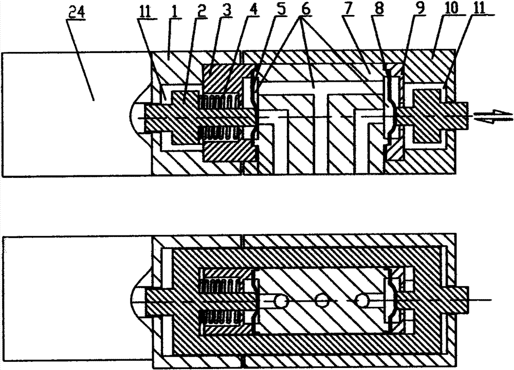
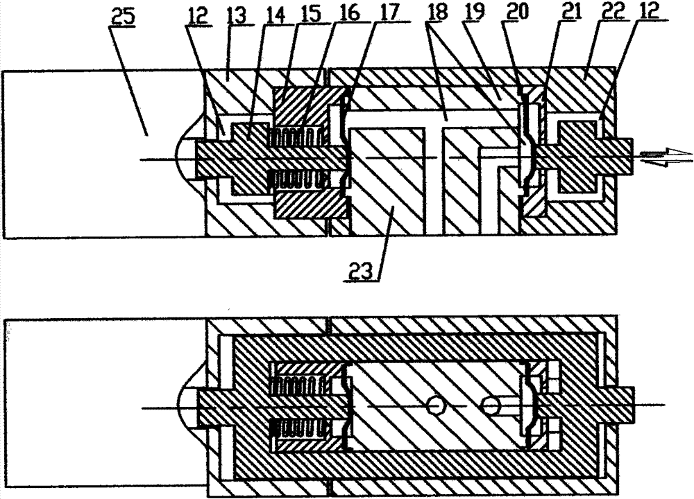
[0015] The realization example of the present invention comprises housing 1, 10, push-pull rod 2, pressure block 3, 9, spring 4, diaphragm 5, 8, valve body 7, driving device 24. Shells 1 and 10 are wrapped on the outside of valve body 7, briquetting blocks 3 and 9, and the periphery of diaphragm 5 and 8 is pressed on valve body 7 through briquetting blocks. There is a cavity 11 between them, and the push-pull rod 2 is located in the cavity 11; the push-pull rod 2 can move back and forth within a certain range in the cavity 11, and the diaphragm 5, 8 and the valve body 7 form an inner cavity 6; the diaphragm 5 , 8 is soft and flexible, and the inner cavity is connected to the outside with three channels, wherein the openings of the first and second channels in the inner body of the cavity 6 are surrounded by valve seats and correspond to the diaphragms 5 and 8 respectively; When there is fluid pressure in the cavity 6, the diaphragms 5 and 8 are under pressure, and some of them...


PUM


Abstract

The invention relates to a directly-operated type diaphragm valve, which comprises a valve body and a driving device arranged outside the valve body, wherein the valve body comprises a valve shell, a valve housing, a diaphragm, a push-and-pull rod and a spring; the shell warps the outside the valve housing; the periphery of the diaphragm is pressed on the valve housing by a pressing block; a cavity is formed among the shell, the pressing block and the valve housing; the push-and-pull rod is positioned in the cavity; the diaphragm and the valve housing enclose an inner cavity; the inner cavityand the outside are connected by at least two channels; the push-and-pull rod is in a frame shape and is sleeved outside a component formed by the pressing block, the valve housing and the diaphragm to improve the pressure resistance of the valve; the spring is arranged between the pressing block and the push-and-pull rod to improve the stress condition of the parts in the valve and improve the stability of the valve; and the push-and-pull rod has an adjustable structure, so that the manufacturing difficulty of the relevant parts is lowered.

Description

technical field [0001] The invention relates to a fluid control element, which is a direct-acting fluid switch valve, which is applied to a fluid control system and has unique advantages in terms of sealing, response time, and inner volume, and is especially suitable for fluid analysis instruments, such as water samples Analyzers, blood analyzers, biochemical analyzers, etc. Background technique [0002] There are many forms of fluid valves, and the structure is different for different applications. Small valves are commonly used in the control pipeline of fluid analysis. The structure is divided into isolated type and non-isolated type, and the movement mode is divided into direct-acting type, lever type and rocker type. The patent No. CN1479030 that adopts the existing isolated type and direct-acting structure discloses. [0003] At present, various similar valves have high manufacturing precision requirements, and the general manufacturing process is difficult to meet t...

Claims


Application Information

Patent Timeline
Patent Type & Authority Patents(China)
IPC IPC(8): F16K11/00F16K7/16F16K27/00
Inventor 白玉申
Owner 东莞市青野电子科技有限公司
Why Eureka
Try Eureka