Laser power monitoring device
A monitoring device and a technology for optical power detection, applied in the field of power devices, can solve problems such as mode instability, and achieve the effects of accurate power monitoring, reduction of stray light, and optimization of optical path structure
- Summary
- Abstract
- Description
- Claims
- Application Information
AI Technical Summary
Problems solved by technology
Method used
Image

Examples
Embodiment Construction
[0020] The preferred embodiments of the present invention will be described below in conjunction with the accompanying drawings. It should be understood that the preferred embodiments described here are only used to illustrate and explain the present invention, and are not intended to limit the present invention.
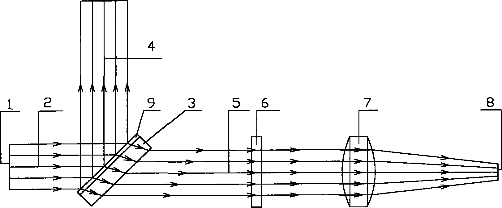
[0021] figure 1 The optical circuit diagram of the laser power detector according to the present invention is shown. As shown in the figure, the laser beam 2 is emitted from the laser exit surface 1 and first reaches the total reflection mirror 3 . The total reflection mirror 3 is coated on its entrance face with a reflective film 9 selected so that a major part of the laser beam 2 is reflected and only a small part is transmitted. Wherein, the reflected beam 4 is output to the laser equipment for normal operation, while the transmitted beam 5 is provided to the photodetection element 8 for power monitoring.
[0022] In one embodiment, the reflective film 9 is a s...
PUM
 Abstract
Description
Claims
Application Information