
Slow wave structure capable of reducing harmonic output of coupled cavity traveling wave tube

A technology of slow wave structure and traveling wave tube, which is applied in the field of slow wave structure, can solve the problems affecting the function of the radar system and the output signal quality of the traveling wave tube, so as to improve the performance, reduce the second harmonic power output, Spectrum clean effect

Active Publication Date: 2012-09-05
HUADONG PHOTOELECTRIC TECHN INST OF ANHUI PROVINCE
View PDF0 Cites 0 Cited by
  • Summary
  • Abstract
  • Description
  • Claims
  • Application Information

AI Technical Summary

Problems solved by technology

Especially when working in the state of gain saturation, the output power of the second harmonic will be considerable, and the output of each harmonic will affect the quality of the output signal of the traveling wave tube, and ultimately affect the function of the radar system

Method used


Image

  • Slow wave structure capable of reducing harmonic output of coupled cavity traveling wave tube
  • Slow wave structure capable of reducing harmonic output of coupled cavity traveling wave tube
  • Slow wave structure capable of reducing harmonic output of coupled cavity traveling wave tube

Examples


Embodiment Construction

[0025] Referring to the accompanying drawings, by describing the embodiments, specific embodiments of the present invention, such as the shape, structure, mutual position and connection relationship between each part, the role and working principle of each part, etc. Further detailed descriptions are provided to help those skilled in the art to have a more complete, accurate and in-depth understanding of the inventive concepts and technical solutions of the present invention.

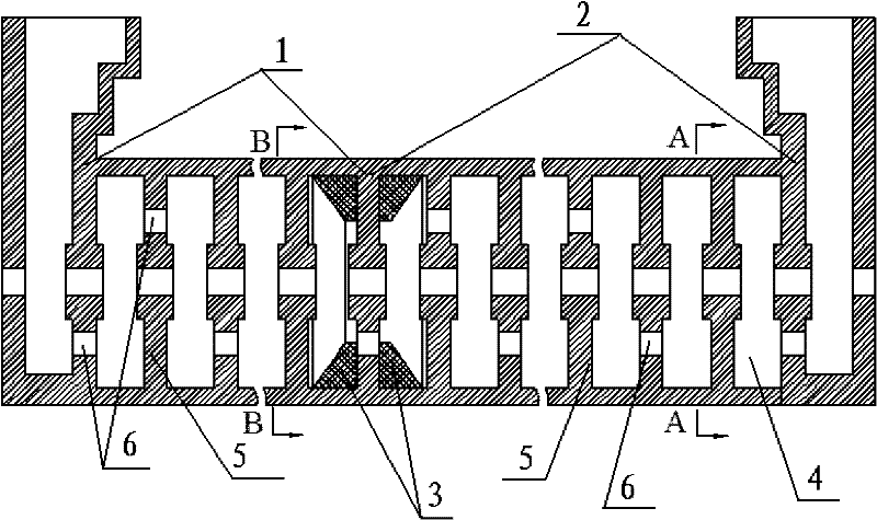
[0026] Such as figure 1 The slow wave structure for reducing the harmonic output of the coupler traveling wave tube includes a driving section 1 and an output section 2 separated by an absorber 3 between the two sections. The driving section 1 and the output section 2 are composed of different numbers of coupling cavities 4 , and adjacent coupling cavities 4 are separated by diaphragms 5 .

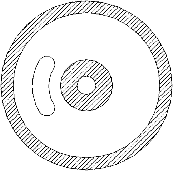
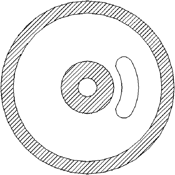
[0027] The diaphragms 5 are all provided with coupling grooves 6 , and the positions of the coupling grooves 6 o...


PUM


Abstract

The invention discloses a slow wave structure capable of reducing harmonic output of a coupler traveling wave tube. The slow wave structure comprises a driving section, an output section and an absorber separating the driving section from the output section, wherein the driving section and the output section respectively comprise different numbers of coupled cavities, the adjacent coupled cavities are separated by diaphragms, coupling slots are arranged on the diaphragms, the positions of the coupling slots on the adjacent diaphragms are different, the phase difference of the coupling slots on the adjacent diaphragms in the coupled cavities of the driving section and the output section is 180 degrees, the phase difference of the coupling slots on the adjacent diaphragms at the tail of a driving end is 90+ / -15 degrees, and the phase difference of the coupling slots on the adjacent diaphragms at the tail of an output end is 90+ / -15 degrees. In the invention, because a coupled cavity slow wave system is improved, the phase of secondary harmonic of negative primary spatial harmonic is advanced, as a result, the output power is greatly attenuated during beam coupling, thereby reducing the power output of the secondary harmonic of the coupled cavity traveling wave tube and optimizing the spectral characteristics.

Description

technical field [0001] The invention belongs to the field of microwave vacuum electronic devices, in particular to a slow wave structure for reducing the harmonic output of a coupler traveling wave tube. Background technique [0002] As a vacuum microwave power amplifier, traveling wave tubes have the advantages of wide frequency band, large gain, high efficiency, and high reliability. They are widely used in various military microwave transmitters and are known as the "heart" of weapons and equipment. According to its slow wave structure, traveling wave tubes can be divided into helical traveling wave tubes, coupled cavity traveling wave tubes, etc. Because the coupling cavity slow-wave structure has good heat dissipation performance and can withstand considerable power, the coupled cavity slow-wave structure is widely used in high-power traveling wave tubes. [0003] Traveling wave tubes with coupled-cavity slow-wave structures are generally used in various radar systems ...

Claims


Application Information

Patent Timeline
Patent Type & Authority Patents(China)
IPC IPC(8): H01J23/24
Inventor 吴华夏江祝苗方卫肖兵沈旭东余峰
Owner HUADONG PHOTOELECTRIC TECHN INST OF ANHUI PROVINCE
Learn More