Wavelength selection method, device and system

A wavelength selection and wavelength technology, applied in the field of optical communication, can solve the problems of difficulty in implementation and popularization, large equipment changes, etc., and achieve the effect of simple implementation, small modification, and convenient implementation and popularization.

Active Publication Date: 2011-05-18
HUAWEI TECH CO LTD
View PDF2 Cites 22 Cited by
  • Summary
  • Abstract
  • Description
  • Claims
  • Application Information

AI Technical Summary

Problems solved by technology

Since the deployment of REC and RE is relatively common at present, adopting this solution will need to replace the exi...

Method used


Image

  • Wavelength selection method, device and system
  • Wavelength selection method, device and system
  • Wavelength selection method, device and system

Examples


Embodiment 1

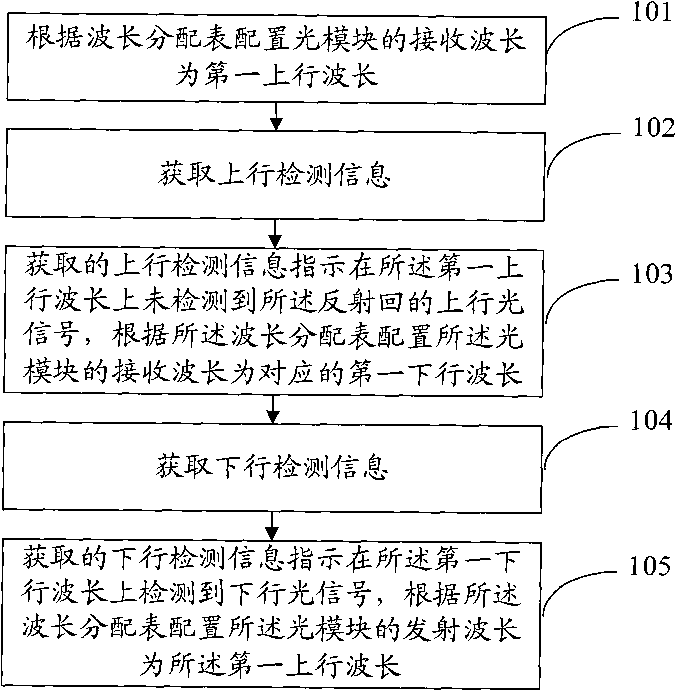
[0045] This embodiment provides a method for selecting a wavelength. Before the method is implemented, a partial mirror can be installed on the remote node (Remote Node, RN) of the ODN to reflect the uplink optical signal during transmission back to the RE. . This method can be deployed on the optical module or on the RE. Such as figure 2 As shown, the method includes:

[0046] Step 101, configure the receiving wavelength of the optical module as the first uplink wavelength according to the wavelength allocation table;

[0047] Step 102, acquiring uplink detection information, the uplink detection information is used to indicate whether an uplink optical signal reflected back by a part of the mirror is detected on the first uplink wavelength;

[0048] Step 103, if the acquired uplink detection information indicates that the reflected uplink optical signal is not detected on the first uplink wavelength, configure the receiving wavelength of the optical module to be the corr...

Embodiment 2

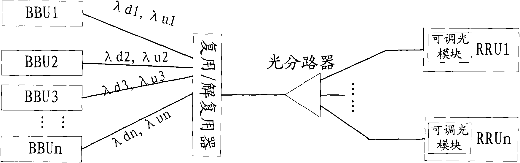
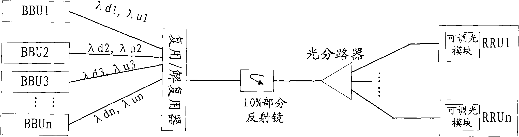
[0055] This embodiment specifically provides a wavelength selection method. Before the method is implemented, a partial mirror can be installed on the RN of the ODN to reflect the uplink optical signal during transmission back to the RE. The system architecture after installing the partial reflector can be as follows image 3 shown. Among them, REC and RE are specifically image 3 Similarly, the corresponding BBU and RRU use a pair of uplink and downlink wavelengths to transmit their uplink optical signals and downlink optical signals. For example, the downlink CPRI optical signal can be transmitted between BBU1 and RRU1 through λd1, and the uplink CRPI optical signal can be transmitted through λu1.

[0056] In fact, there are also optical modules in the BBU, but because the method in this embodiment does not need to change the BBU, so in image 3 not shown in. Because the method provided in this embodiment is applicable to be deployed on a dimmable light module, so imag...

Embodiment 3

[0089] This embodiment specifically provides a wavelength selection method. Before the method is implemented, a partial reflector may also be installed on the RN of the ODN to reflect the uplink optical signal during transmission back to the RE. The schematic diagram of part of the system construction after installing the partial reflector can also refer to image 3 . The main difference between embodiment 3 and embodiment 1 is that the method for selecting the wavelength provided is implemented inside the RRU. Both the transmit and receive wavelengths of the tunable transmitter and tunable receiver in the tunable optical module in this implementation can be adjusted, and the RRU can set the transceiver wavelength of the tunable optical module through a wavelength setting (WL_SET) signal.

[0090] For the workflow of BBU1 in this embodiment, refer to the workflow of BBU1 in Embodiment 2.

[0091] The following describes the workflow of RRU1 corresponding to BBU1 in this embo...


PUM


Abstract

The embodiment of the invention discloses a wavelength selection method, a wavelength selection device and a wavelength selection system, relates to the field of optical integration and solves the technical problem that the conventional equipment is greatly modified in the process of transmitting common public radio interface (CPRI) optical signals through an optical distribution network (ODN) inthe prior art. The method in the embodiment of the invention comprises the following steps of: configuring the receiving wavelength of an optical module as a first uplink wavelength according to a wavelength allocation list; acquiring uplink detection information for indicating whether an uplink optical signal reflected by a partial reflector is detected on the first uplink wavelength; if the acquired uplink detection information indicates that the reflected uplink optical signal is not detected, configuring the receiving wavelength of the optical module as a corresponding first downlink wavelength; acquiring downlink detection information; and if the acquired downlink detection information indicates that a downlink optical signal is detected, configuring the transmitting wavelength of the optical module as the first uplink wavelength. The embodiment of the invention is mainly applied to wavelength division multiplexing (WDM) scenes.

Description

technical field [0001] The present invention relates to optical communication technology, in particular to a wavelength selection method, device and system. Background technique [0002] The common public radio interface (Common Public Radio Interface, CPRI) is an interface standard between a radio equipment controller (Radio Equipment Controller, REC) in a wireless base station device and a radio equipment (Radio Equipment, RE) in an access device. A CPRI link refers to a bidirectional link between a directly connected REC and RE or two RE nodes. A CPRI link includes a master port, a bidirectional link, and a slave port. The direction from the master port of the CPRI link to the slave port is the downlink direction; the direction from the slave port to the master port of the CPRI link is the uplink direction. [0003] REC and RE use point-to-point communication. When the RE establishes a CPRI link with the REC, in order to ensure that the port operating rates of the REC ...

Claims


Application Information

Patent Timeline
IPC IPC(8): H04Q11/00H04B10/08H04B10/071
Inventor 叶飞
Owner HUAWEI TECH CO LTD
Why Eureka
Try Eureka