Method of reducing the attachment of slag when piercing a workpiece with a laser beam, and laser machining head

A laser processing head and laser beam technology are used in the fields of reducing the adhesion of slag when the laser beam is pierced into a workpiece and the laser processing head, and can solve the problems of inability to prevent slag and the like

Inactive Publication Date: 2011-05-18
TRUMPF WERKZEUGMASCHINEN GMBH & CO KG
View PDF10 Cites 18 Cited by
  • Summary
  • Abstract
  • Description
  • Claims
  • Application Information

AI Technical Summary

Problems solved by technology

However, such an arrangement also cannot preve

Method used


Image

  • Method of reducing the attachment of slag when piercing a workpiece with a laser beam, and laser machining head
  • Method of reducing the attachment of slag when piercing a workpiece with a laser beam, and laser machining head
  • Method of reducing the attachment of slag when piercing a workpiece with a laser beam, and laser machining head

Examples


Embodiment Construction

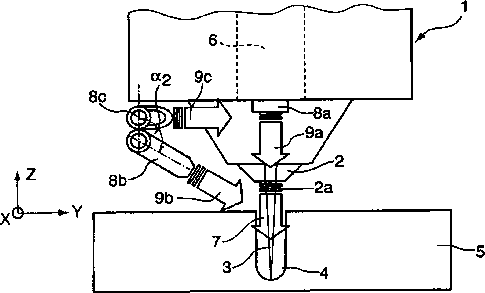
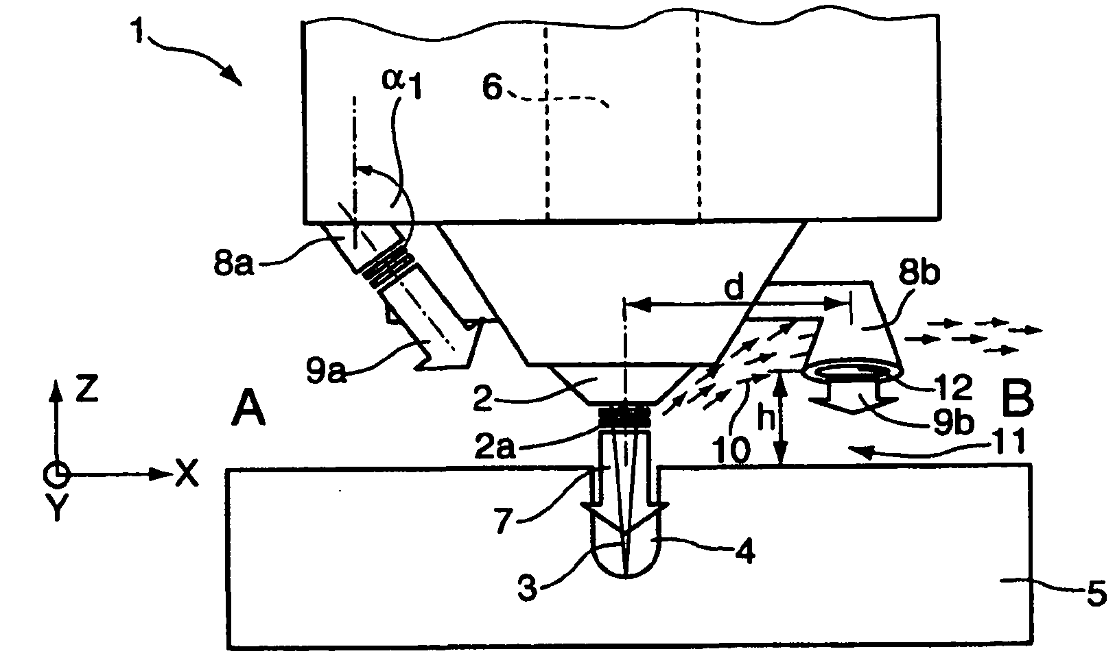
[0025] Figure 1a , b show the laser processing head 1 in side views along the X-axis or the Y-axis of the XYZ coordinate system, respectively. The laser processing head 1 has a laser cutting nozzle 2 through which a laser beam 3 is emitted through a nozzle opening 2a of the laser cutting nozzle, and the laser beam produces a puncture site 4 (puncture hole) on the workpiece 5 . The laser cutting nozzle 2 is also connected to a pressure chamber 6 of the laser processing head 1 which is filled with a cutting gas, in particular oxygen, in order to direct the cutting gas flow 7 through the nozzle opening 2a towards the puncture site 4 .

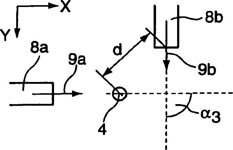
[0026]The first gas nozzle 8a is arranged on the laser processing head 1 at a distance of about 40 mm from the puncture site 4 on the first side A of the laser cutting nozzle 2 to generate a first additional gas flow 9a which is at the first side A of the puncture site 4. Side A hits the workpiece 5 to blow the slag 10 away from the puncture site...


PUM


Abstract

The invention relates to a method of reducing the attachment of slag (10) when piercing a workpiece (5) with a laser beam (3), during which at least a first additional stream of gas (9a) is directed onto the workpiece (5) at a first angle (a1) to the direction of laser radiation (Z) and impinges on the workpiece (5) on a first side (A) of a piercing point (4) and/or at the piercing point (4) itself, in order to blow slag (10) away from the piercing point (4). At least a second stream of additional gas (9b, 9b', 9b'') is directed onto the workpiece (5) at a second angle (a2) to the direction of laser radiation (Z) and impinges on the workpiece (5) on a second side (B) of the piercing point (4), opposite from the first side (A), at a distance from the piercing point (4), wherein the second additional stream of gas (9b, 9b', 9b'') is aligned at an angle to the first stream of additional gas (9a) with respect to a plane (X, Y) that is perpendicular to the direction of laser radiation (Z), in order to create a gas cushion (11) between the slag (10) blown away by the first additional stream of gas (9a) and the workpiece (11). The invention also relates to a laser machining head (1) for carrying out the method.

Description

technical field [0001] The invention relates to a method for reducing the adhesion of slag when a laser beam penetrates into a workpiece, in which method at least one first additional gas flow is directed towards the workpiece at a first angle with respect to the direction of the laser beam and at a a first side of the piercing site and / or hitting the workpiece at the piercing site itself to blow slag away from the piercing site, and a laser processing head for carrying out the method, comprising: a laser cutting nozzle, A laser beam and cutting gas flow are directed through a nozzle opening of the laser cutting nozzle to a puncturing site on the workpiece during piercing; and at least one first gas nozzle disposed on a first side of the laser cutting nozzle and opposite to oriented at a first angle of the laser beam axis to generate a first additional air flow that hits the workpiece on a first side of the piercing site and / or at the piercing site itself to dislodge slag from...

Claims


Application Information

Patent Timeline
IPC IPC(8): B23K26/14
CPCB23K26/1405B23K26/16B23K26/142
Inventor A·谢尔阿戈斯基F·塞普M·施洛特尔
Owner TRUMPF WERKZEUGMASCHINEN GMBH & CO KG
Why Eureka
Try Eureka