Soldering bit mechanism of automatic soldering robot

A technology of soldering iron tips and robots, which is applied in the direction of soldering irons, welding equipment, auxiliary devices, etc., can solve the problems of difficult to control precise travel, wear, and inflexibility, and achieve the effect of reducing wear and prolonging service life

Active Publication Date: 2011-05-25
CHANGZHOU MINGSEAL ROBOT TECH CO LTD
View PDF1 Cites 6 Cited by
  • Summary
  • Abstract
  • Description
  • Claims
  • Application Information

AI Technical Summary

Problems solved by technology

The control of the gimbal arm with this structure is not precise and stable enough
The soldering iron head of the automatic soldering robot disclosed in Japanese patent document JP 3226370 is controlled by an up-down direction movement mechanism and a left-right direction movement mechanism, which can control the position of the soldering iron head more accurately. The soldering iron head with this structure cannot deflect the angle and is still not flexible enough
At the same time, there is an obvious defect in the above two kinds of soldering equipment. It lacks a special mechanism for controlling the short-range movement of the soldering iron tip. Because when the soldering iron tip moves to the soldering working position for soldering, it will rise to move to the next soldering working position. When welding a large number of the same horizontal working position, the soldering iron tip still needs to be driven by the universal arm or the up and down movement mechanism, so that on the one hand, it is difficult to control the small distance accurately, and on the other hand, the universal arm or the up and down movement mechanism moves frequently It is easy to cause wear and affect the service life of welding equipment

Method used


Image

  • Soldering bit mechanism of automatic soldering robot
  • Soldering bit mechanism of automatic soldering robot
  • Soldering bit mechanism of automatic soldering robot

Examples


Embodiment 1

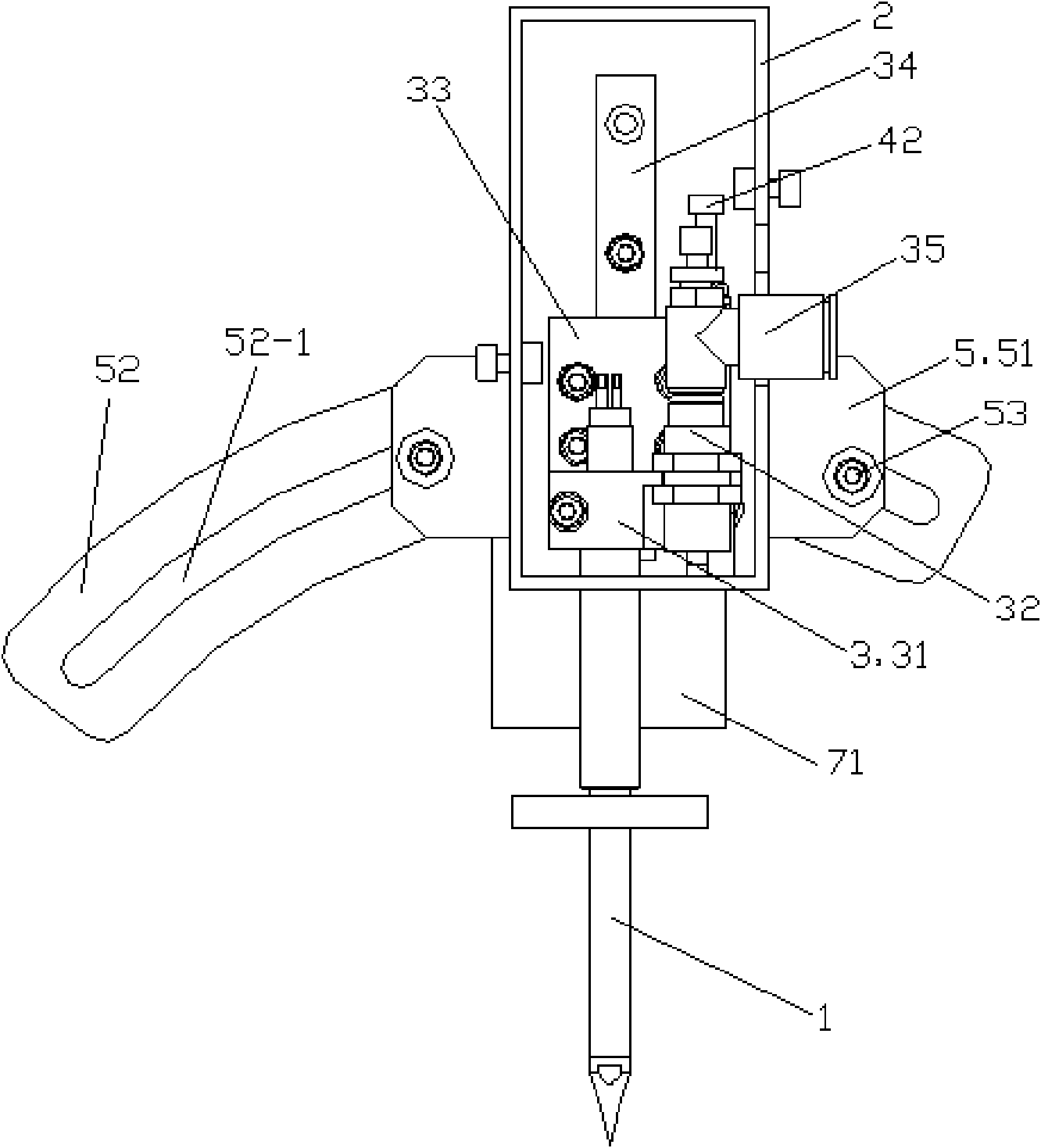
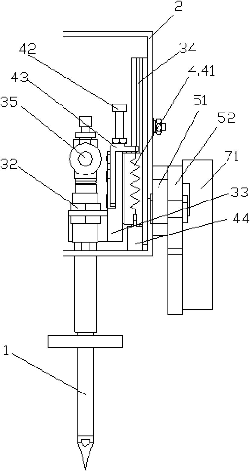
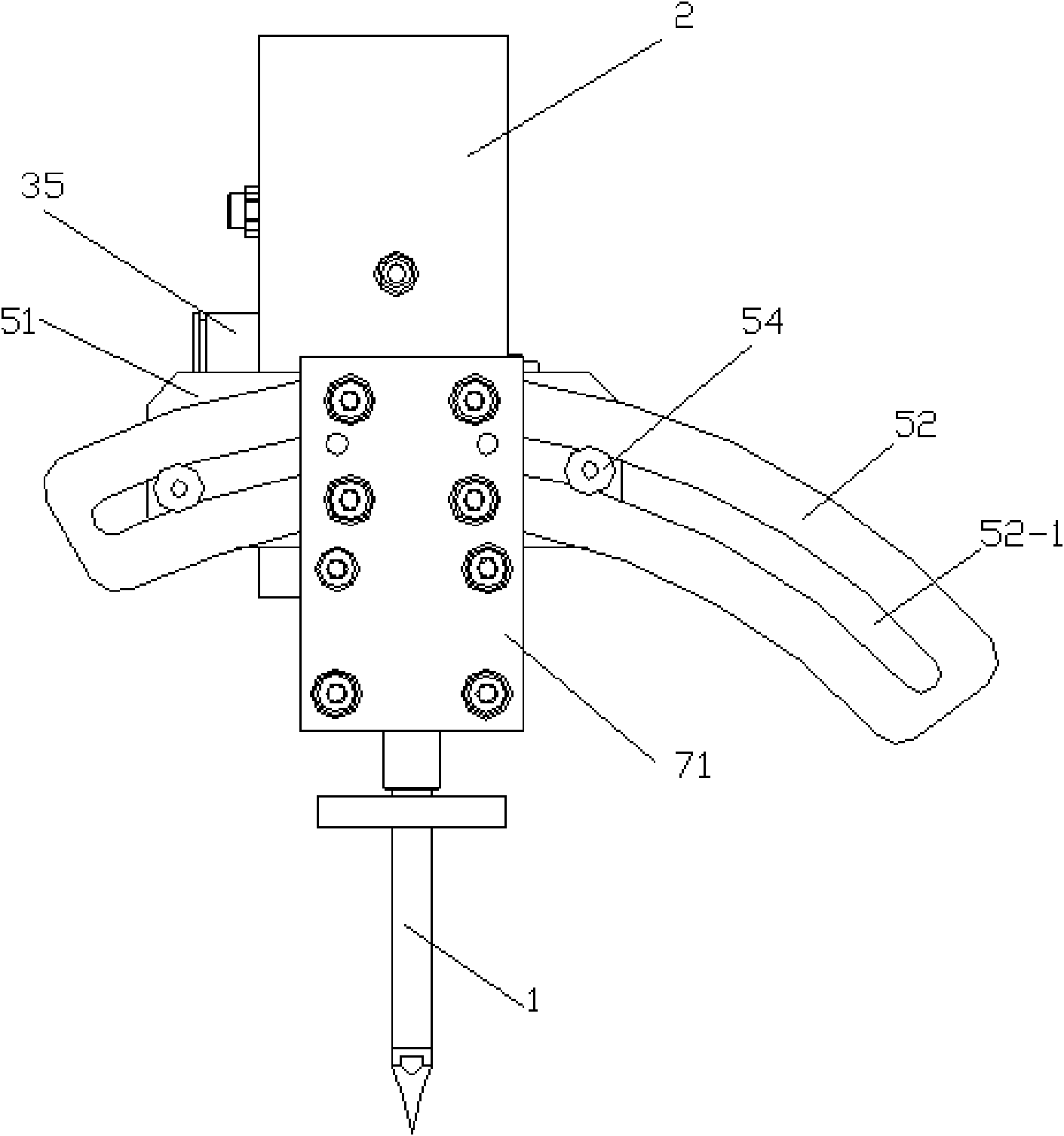
[0023] See Figure 4 , the soldering iron tip mechanism of the automatic soldering robot of this embodiment is fixed on the Z-axis module 7 of the automatic soldering robot 6 that controls the movement in the up and down direction through the Z-axis connecting block 71 .

[0024] See Figure 1 to Figure 3 , The soldering iron tip mechanism of the automatic soldering robot includes a soldering iron tip 1, a box body 2 and a soldering iron tip movement mechanism. The moving mechanism of the soldering iron tip includes a moving device 3 , a pressure regulating device 4 and an angle regulating device 5 . The moving device 3 and the pressure regulating device 4 are arranged in the box body 2 .

[0025] The moving device 3 includes a connecting block 31 , a cylinder 32 , a slide plate 33 , a linear slide rail 34 and a speed regulating joint 35 . The connecting block 31 connects the upper end of the soldering iron tip 1 with the cylinder body of the cylinder 32, and the connecting...


PUM


Abstract

The invention discloses a soldering bit mechanism of an automatic soldering robot. The soldering bit mechanism comprises a soldering bit and is fixed on a Z-axis module of the automatic soldering robot, wherein the Z-axis module is used for controlling upward and downward movements; and the soldering bit is connected with a box body. The soldering bit mechanism also comprises a soldering bit moving mechanism for controlling the soldering bit, wherein the soldering bit moving mechanism comprises a shifting device which is connected with the soldering bit and arranged in the box body; the shifting device comprises a connection block, a cylinder, a sliding plate and a linear slide rail; the connection block connects the upper end of the soldering bit with the body of the cylinder and is also connected with the sliding plate; and the sliding plate is connected with the linear slide rail in a sliding manner. The soldering bit mechanism has the following beneficial effects: the shifting device of the soldering bit moving mechanism disclosed by the invention adopts the cylinder connected with the soldering bit as the power for driving the soldering bit to move up and down frequently and the soldering bit is driven to quickly and stably move through stretching/withdrawing of the body of the cylinder until a soldering work point is finished, thus avoiding the problem that the Z-axis module moved up and down frequently in the work process before and reducing the abrasion of the Z-axis module.

Description

technical field [0001] The invention relates to an accessory of a soldering robot, in particular to a soldering iron tip mechanism of an automatic soldering robot. Background technique [0002] The soldering machine is mainly used for tinning the PCB board with electronic components inserted, that is, the PCB board is placed on the tin surface in the tin furnace to let the liquid tin stick to the insertion hole of the PCB board, so that the electronic components are soldered to the PCB board. Soldering machines mainly include immersion welding machines and wave soldering machines: 1. Immersion welding machines, which are about to fix the container for storing tin liquid, let the circuit board move downward, so that the welding surface reaches below the surface of the tin liquid, so as to achieve soldering the goal of. The disadvantage of this is that if the circuit board is moved up and down, it is prone to short circuit and soldering is not full, and the area of ​​the sold...

Claims


Application Information

Patent Timeline
Patent Type & Authority Applications(China)
IPC IPC(8): B23K3/02B23K3/08
Inventor 曲东升孙岩闵继江李长峰许国华
Owner CHANGZHOU MINGSEAL ROBOT TECH CO LTD
Why Eureka
Try Eureka