Rear energy storage type super-high speed plasticizing injection device

An injection device and ultra-high-speed technology, applied in the field of plasticizing injection devices, can solve the problems of low control precision, difficult acceleration, high energy consumption, etc., and achieve the effect of solving difficult control, high energy consumption, and simple connection structure

Active Publication Date: 2011-05-25
BEIJING UNIV OF CHEM TECH
View PDF1 Cites 6 Cited by
  • Summary
  • Abstract
  • Description
  • Claims
  • Application Information

AI Technical Summary

Problems solved by technology

The technical problem to be solved by the present invention is to overcome the problems of large energy consumption, low control precision, and difficult acceleration existing in the current ultra-high-speed injection molding machine, so as to provide an ultra-high-speed injection molding machine with simple structure, convenient operation, stable operation, and high cost performance

Method used


Image

  • Rear energy storage type super-high speed plasticizing injection device
  • Rear energy storage type super-high speed plasticizing injection device
  • Rear energy storage type super-high speed plasticizing injection device

Examples


Embodiment Construction

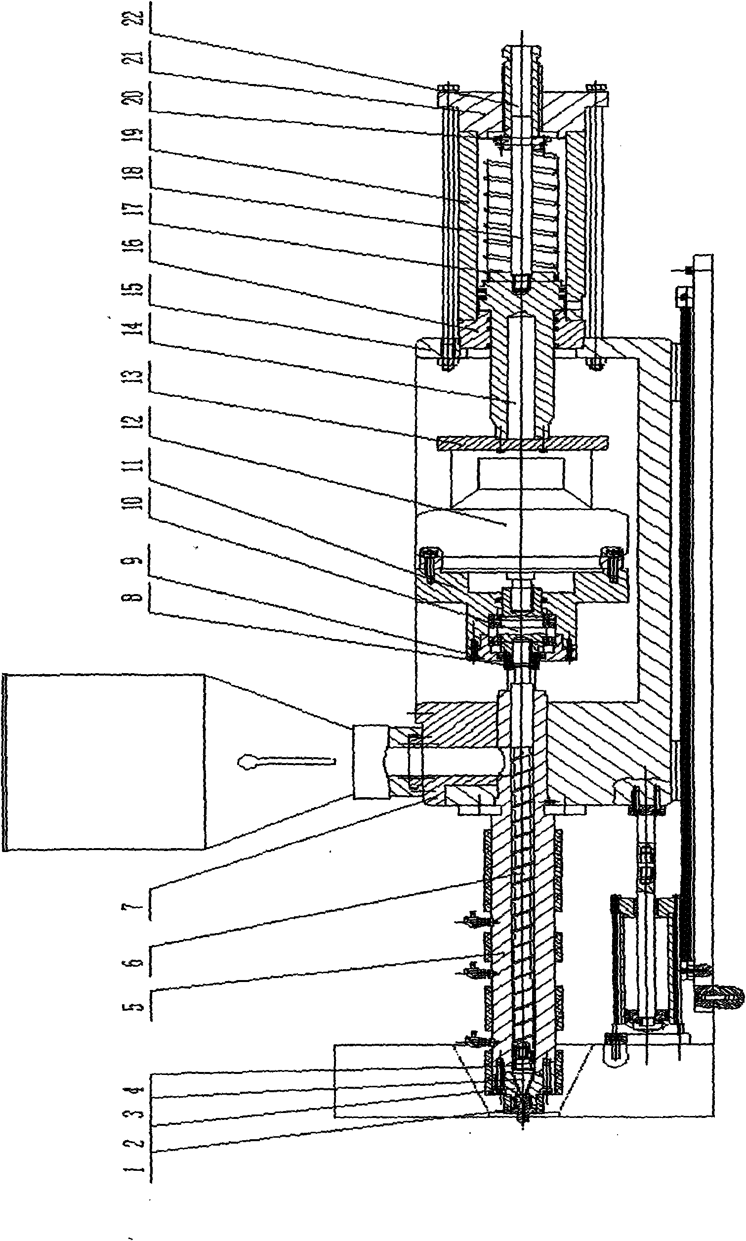
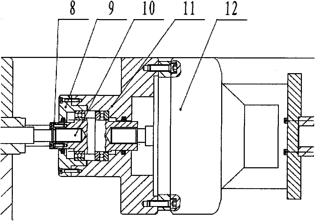
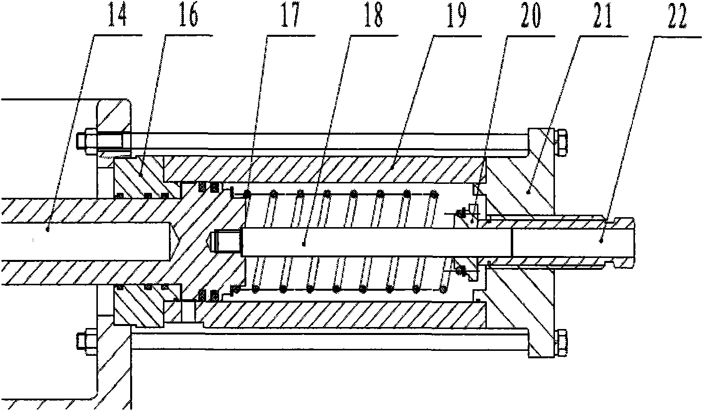
[0021] Such as figure 1 As shown, the energy storage type ultra-high-speed plasticizing injection device is mainly composed of: nozzle 1, barrel 5, screw 6, hydraulic motor 12, injection piston 14, injection seat 15, injection cylinder front cover 16, injection cylinder body 19, Injection cylinder back cover 21, spring 17, adjustment sleeve 22 are formed. Wherein, the barrel 5, the injection seat 15, the hydraulic motor 12, the injection piston 14, the spring and the adjustment sleeve 22 are sequentially aligned and connected with each other. The injection seat 15 can slide relatively, the feeding sleeve 7 is placed on the injection seat 15 , the tail of the screw rod 6 is connected with the spline shaft 10 through the spline, and the hydraulic motor 12 is connected with the screw rod 6 through the spline shaft 10 . The injection cylinder is placed on the injection seat 15 rear, and the spring 17 is contained in the injection cylinder, and the spring 17 can be freely compress...


PUM


Abstract

The invention discloses a rear energy storage type super-high speed plasticizing injection device, and belongs to the field of high molecular material machining equipment. The device mainly comprises a nozzle, a barrel, a screw, a heating ring, a charging bucket, an injection table, a charging bucket seat, a hydraulic motor, an injection oil cylinder and a spring adjusting device, wherein the nozzle, the barrel, the charging bucket seat, the hydraulic motor and the injection oil cylinder are connected in alignment with an axis in turn; the super-high speed plasticizing injection device is substantially the same as the plasticizing injection device of the normal injection molding machine; the injection oil cylinder consists of a cylinder barrel, an injection piston, an injection piston rod, a pressure sensor and a speed increasing spring; the speed increasing spring is positioned in an oil chamber of the injection oil cylinder and is close to the tail end; and one end of the speed increasing spring is fixed with the end face of the injection piston, and the end close to the tail end of the injection oil cylinder is a free end or is connected with the spring adjusting device. Energyis stored by the rear control spring energy storage device, and is released during injection to improve the screw injection speed, so that the technical requirement of super-high speed injection is met, and the defects of high cost, difficulty in maintenance, high energy consumption and the like of the conventional super-high speed injection molding machine are overcome well.

Description

technical field [0001] The invention relates to a plasticizing injection device of an injection molding machine in polymer processing and molding equipment, in particular to a plasticizing injection device for realistic ultra-high-speed injection. Background technique [0002] With the development of society and the progress of science and technology, people put forward the urgent requirement of "ultra-light, ultra-thin, ultra-precision" for polymer material products. In order to meet this requirement, ultra-high-speed injection molding technology came into being. Generally speaking, ultra-high-speed injection molding has two meanings, one refers to the molding of thin-walled products at ultra-high injection speed, and the other refers to the ultra-high-speed cycle molding process, that is, the molding cycle is short. [0003] Generally speaking, those with an injection speed below 300mm / s are called traditional injection machines, those with an injection speed between 300m...

Claims


Application Information

Patent Timeline
Patent Type & Authority Applications(China)
IPC IPC(8): B29C45/54
Inventor 谢鹏程郭小龙丁玉梅杨卫民
Owner BEIJING UNIV OF CHEM TECH
Why Eureka
Try Eureka