Heating furnace supporting beam and heat-resistant bearer fixing structure

A technology for fixing structures and supporting beams, applied in the field of supporting beam structures, can solve problems such as the leakage of cooling bodies of supporting beams that cannot be overcome, and achieve the effects of reducing the number of shutdowns for maintenance, improving service life, and having a simple structure.

Active Publication Date: 2012-06-27
CERI PHOENIX INDAL FURNACE CO TD +1
View PDF1 Cites 0 Cited by
  • Summary
  • Abstract
  • Description
  • Claims
  • Application Information

AI Technical Summary

Problems solved by technology

Among them, some arc-shaped transverse grooves are opened on the base of the slide rail, and the direction of the groove is basically perpendicular to the axial direction of the bottom surface. The rail is still directly fixed on the furnace reinforcement tube (support beam) by welding, although it can eliminate some forces caused by temperature differences and different thermal expansion coefficients, it still cannot overcome the above-mentioned support beam under high temperature operating conditions. Problems of cracking and cooling body leakage inside the support beam

Method used


Image

  • Heating furnace supporting beam and heat-resistant bearer fixing structure
  • Heating furnace supporting beam and heat-resistant bearer fixing structure
  • Heating furnace supporting beam and heat-resistant bearer fixing structure

Examples


Embodiment 1

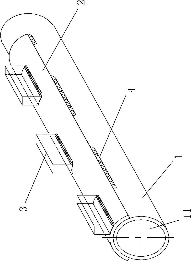
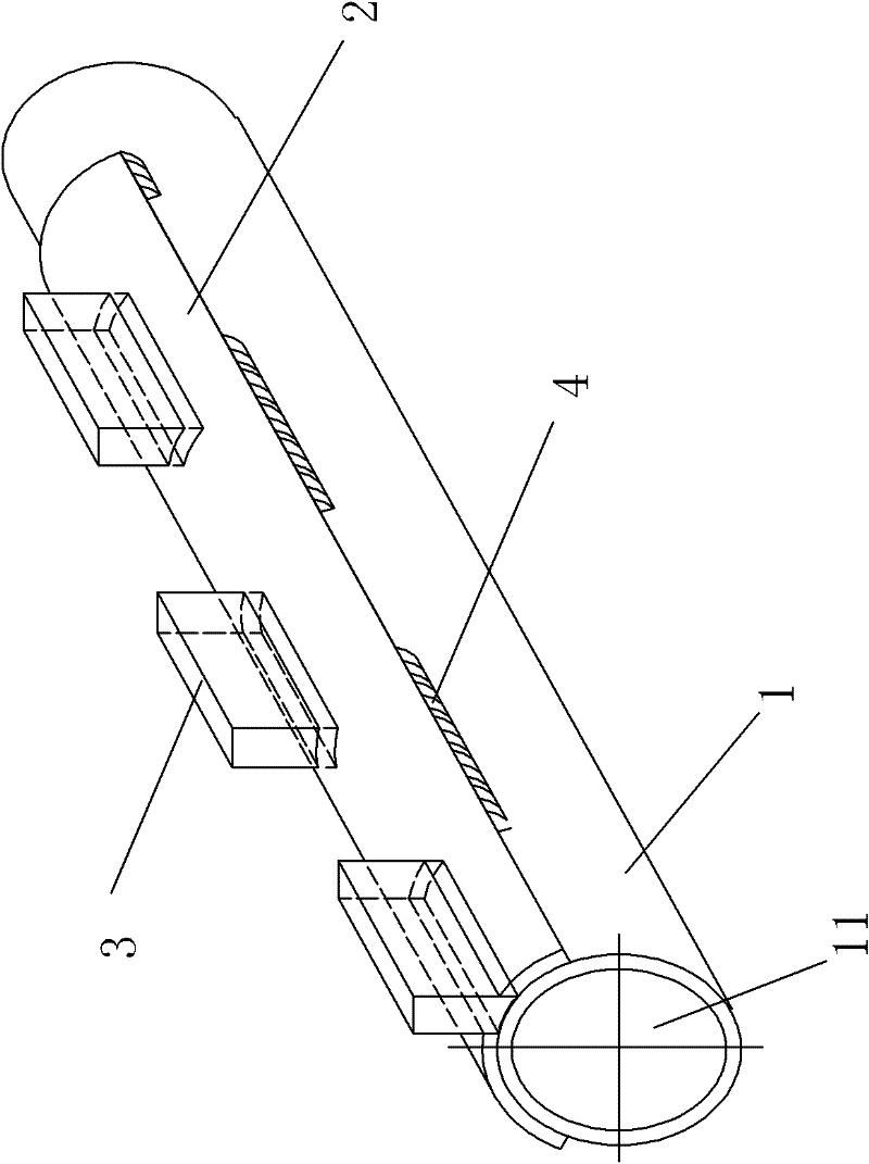
[0029] figure 1 It is a schematic diagram of the first embodiment of the fixing structure of the heating furnace support beam and the heat-resistant pad of the present invention. Such as figure 1 As shown, the fixing structure of the heating furnace support beam and the heat-resistant cushion block proposed by the present invention includes: a horizontal support beam 1, a cooling channel 11 is arranged in the horizontal support beam 1; a backing plate is provided along the length direction of the horizontal support beam 1 2. The backing plate 2 has a radian matching the horizontal support beam 1, forming a long arc backing plate, and is arranged on the upper half of the horizontal support beam 1; the heat-resistant pad 3 is fixed on the backing plate 2 on. The heat-resistant block 3 is used to hold up the steel billet, and the high temperature of the steel billet is directly transmitted to the heat-resistant block 3. Since the average temperature of the backing plate 2 close...

Embodiment 2

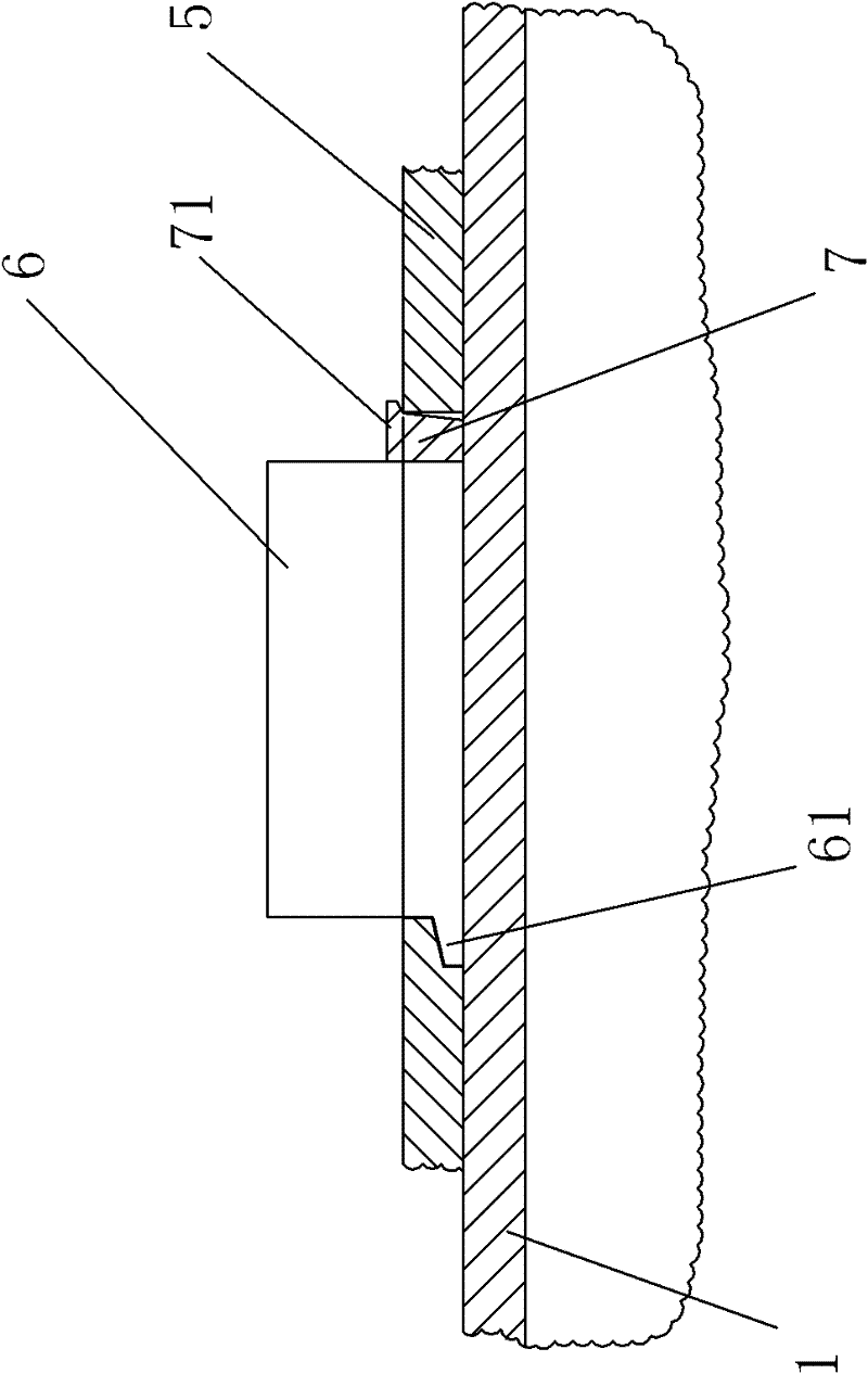
[0033] figure 2 It is a schematic diagram of the second embodiment of the fixing structure of the heating furnace support beam and the heat-resistant pad of the present invention; image 3 It is a partial cross-sectional schematic diagram along the axial direction of the horizontal support beam. Such as figure 2 , 3 As shown, in another embodiment of the present invention, the backing plate 5 is provided with a plurality of through holes, and the heat-resistant spacer 6 is embedded and fixed in the through holes.

[0034] A specific solution is that the periphery of the heat-resistant pad 6 is intermittently welded and fixedly connected to the periphery of the through hole of the backing plate 5 .

[0035] Another feasible solution is that a block 7 is embedded and fixed between the heat-resistant pad 6 and the through hole, and the heat-resistant pad 6 is embedded and fixed in the through hole of the backing plate 5 . In order to ensure the firmness of the connection, i...


PUM


Abstract

The invention provides a heating furnace supporting beam and heat-resistant bearer fixing structure, which comprises a horizontal supporting beam, a base plate and a heat-resistant bearer, wherein a cooling channel is formed inside the horizontal supporting beam; the base plate is provided with radian matched with the horizontal supporting beam and is arranged on the horizontal supporting beam along the length direction of the horizontal supporting beam; discontinuous welded and fixed connection is formed between the base plate and the horizontal supporting beam; and the heat-resistant beareris fixed on the base plate. The structure effectively overcomes the defects in the prior art, and the horizontal supporting beam cannot be cracked due to different thermal expansions of the heated heat-resistant bearer and the horizontal supporting beam. The structure is simple in structure, and can effectively avoid a water leakage accident that the horizontal supporting beam is cracked due to different thermal expansion coefficients of the heat-resistant bearer and the horizontal supporting beam; the service life of the equipment is prolonged, the blowout maintenance times of the heating furnace is reduced, and the production efficiency is improved.

Description

technical field [0001] The invention relates to a supporting beam structure of a heating furnace of a rolling mill, in particular to a fixing structure of a heating furnace supporting beam and a heat-resistant pad. Background technique [0002] In the iron and steel plant, the steel billet must be heated to a temperature of 1150-1300°C in the heating furnace. To make the hot steel billet be heated in the heating furnace, and the temperature of each part be uniform, the steel billet must be lifted in the heating furnace to The upper and lower surfaces of the billet are heated evenly at the same time. For this reason, a high-temperature-resistant metal pad is set on the top of the support beam, and the steel billet is placed on the heat-resistant metal pad, and because the temperature of the steel billet is high, the support beam that supports the billet is injected into the inside with cooling water or a mixture of soda and water. cool down. But in the known structure, usua...

Claims


Application Information

Patent Timeline
Patent Type & Authority Patents(China)
IPC IPC(8): C21D9/70
Inventor 王礼宏李秀敏周庆玮张垚
Owner CERI PHOENIX INDAL FURNACE CO TD
Why Eureka
Try Eureka