
Gas mixing control device

A mixing control and airflow mixing technology, which is applied in the direction of charging system, carburetor, engine components, etc., can solve the problems of reduced engine life, high engine temperature, and insufficient gas mixing, so as to reduce engine temperature and improve service life. The effect of life and work performance improvement

Inactive Publication Date: 2011-05-25
LONCIN MOTOR
View PDF7 Cites 0 Cited by
  • Summary
  • Abstract
  • Description
  • Claims
  • Application Information

AI Technical Summary

Problems solved by technology

[0004] The gas flow of the current gas mixing control device is controlled by a diaphragm or a mechanical device, which cannot automatically control the mixing ratio of the gas flow and air. The gas mixing is insufficient, and the gas intake volume cannot be automatically adjusted through the power of the engine, which consumes a lot of energy. , the engine temperature is high, reducing the service life of the engine

Method used


Image

  • Gas mixing control device
  • Gas mixing control device
  • Gas mixing control device

Examples


Embodiment Construction

[0038] The invention discloses a gas mixing control device, which can automatically adjust the amount of gas intake through the power of the engine.

[0039] The following will clearly and completely describe the technical solutions in the embodiments of the present invention with reference to the accompanying drawings in the embodiments of the present invention. Obviously, the described embodiments are only some, not all, embodiments of the present invention. Based on the embodiments of the present invention, all other embodiments obtained by persons of ordinary skill in the art without making creative efforts belong to the protection scope of the present invention.

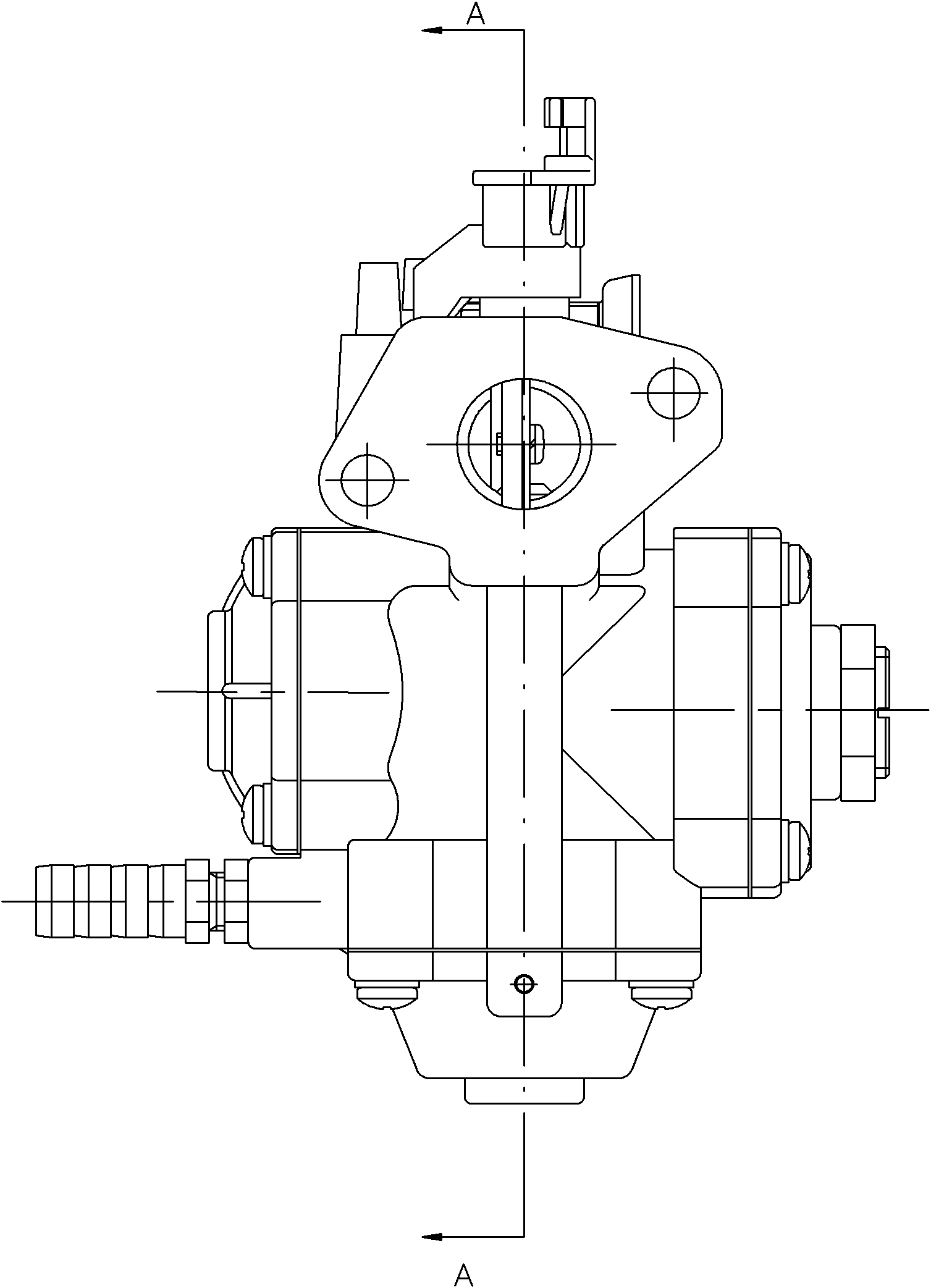
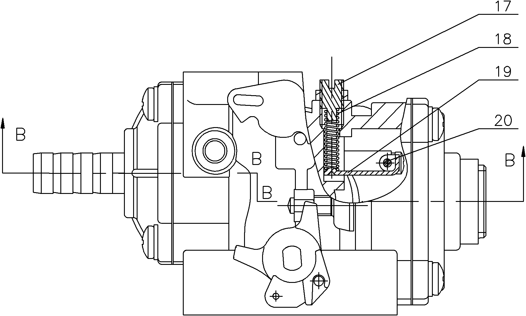
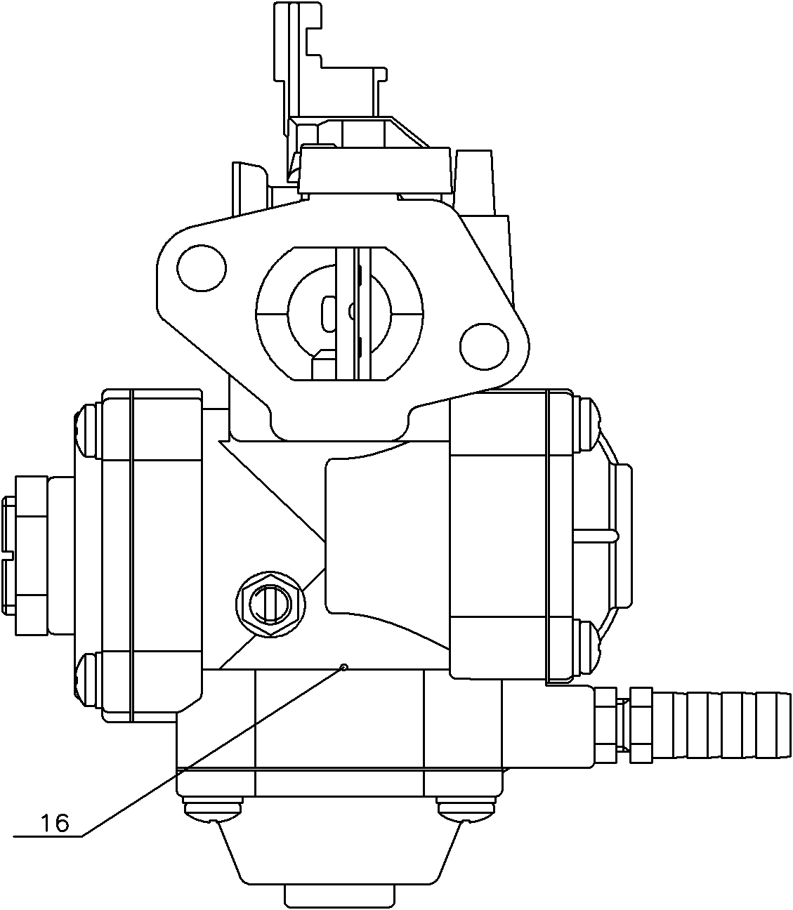
[0040] see Figure 1-Figure 4 , figure 1 It is a schematic diagram of the front view structure of the gas mixing control device provided by the embodiment of the present invention, figure 2 It is a schematic top view structure diagram of the gas mixing control device provided by the embodiment of the present ...


PUM


Abstract

The invention discloses a gas mixing control device, which comprises a gas mixing control body, a lower mixing control body cover, a needle valve diaphragm, a needle valve, a needle cylinder, a needle valve sleeve and a return spring, wherein the two ends of the gas mixing control body are provided with a choke valve part and a throttle valve part respectively; a gas flow mixing channel with a throat is formed between the choke valve part and the throttle valve part; a diaphragm moving cavity is formed between the lower mixing control body and the gas mixing control body, and is divided into an upper diaphragm moving cavity and a lower diaphragm moving cavity by the needle valve diaphragm; the upper diaphragm moving cavity is communicated with the atmosphere; the needle cylinder is connected with the needle valve diaphragm; a gas storage cavity is formed above the needle cylinder; the needle valve sleeve is communicated with the gas storage cavity and the gas flow mixing channel respectively; one end of the needle valve is extended into the needle valve sleeve; the lower diaphragm moving cavity is communicated with the gas flow mixing channel behind the throttle valve part; and the return spring is arranged between the needle valve diaphragm and the lower mixing control body cover. The gas mixing control device can automatically adjust the inflow of a fuel gas by the power of an engine, has low energy consumption, reduces the temperature of the engine and prolongs the service life of the engine.

Description

technical field [0001] The invention relates to the technical field of gas engines, in particular to a gas mixing control device. Background technique [0002] An engine, also known as an engine, is a machine that converts one form of energy into another, more useful energy, usually chemical energy into mechanical energy. Sometimes it applies to both the power generating unit and the entire machine including the power unit. The engine can include a fuel engine and a gas engine. As the market oil price rises, the cost of the gasoline engine is getting higher and higher, and it is also very polluting to the air. As a kind of economical and environment-friendly power equipment, gas engine is more and more recognized by people, and has been widely used in power, starting and other industries. The principle of the gas engine is: gas and combustion air are mixed in the mixer and then injected into the combustion chamber of the gas engine to ignite and perform work, converting ch...

Claims


Application Information

Patent Timeline
Patent Type & Authority Applications(China)
IPC IPC(8): F02M7/17
Inventor 杨开会刘隆平李云兵
Owner LONCIN MOTOR
Learn More