
Rotor-groove harmonic analysis based method for identifying temperature of sensorless rotor for submersible motor

A technology for sensor rotors and submersible motors, which is applied to thermometers, thermometers, instruments, etc. that use electric/magnetic components that are directly sensitive to heat, and can solve problems such as strong dependence on motor parameters

Inactive Publication Date: 2011-05-25
HARBIN INST OF TECH
View PDF2 Cites 9 Cited by
  • Summary
  • Abstract
  • Description
  • Claims
  • Application Information

AI Technical Summary

Problems solved by technology

[0004] The purpose of the present invention is to solve the problem in the prior art that the identification of the rotor temperature of the submersible motor is highly dependent on the motor parameters, and to provide a sensorless rotor temperature identification method for the submersible motor based on harmonic analysis of the rotor slot

Method used


Image

  • Rotor-groove harmonic analysis based method for identifying temperature of sensorless rotor for submersible motor
  • Rotor-groove harmonic analysis based method for identifying temperature of sensorless rotor for submersible motor
  • Rotor-groove harmonic analysis based method for identifying temperature of sensorless rotor for submersible motor

Examples


specific Embodiment approach 1

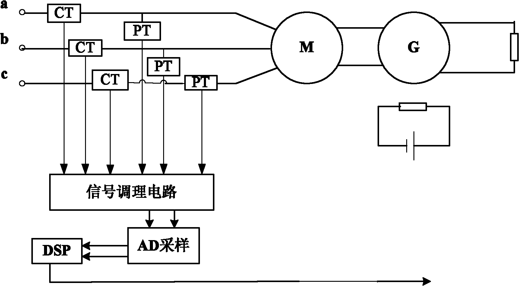
[0040] Specific implementation mode one: the following combination figure 1 with figure 2 Describe this implementation mode, this implementation mode comprises the following steps:

[0041] Step 1: collecting the three-phase stator voltage and three-phase stator current of the submersible motor;

[0042] Step 2: respectively process the three-phase stator voltage and the three-phase stator current through the signal conditioning circuit, and use the processed signals as the stator original current input signal and the stator original voltage input signal;

[0043] Step 3: Perform harmonic analysis on the frequency spectrum of the stator original current input signal using fast Fourier transform FFT to obtain the fundamental wave and each harmonic amplitude of the stator three-phase current, that is, to obtain the rotor slot harmonics of the submersible motor f sh for:

[0044] Formula one: f sh = f 1 ...

specific Embodiment approach 2

[0065] Embodiment 2: This embodiment is a further description of Embodiment 1. The fast Fourier transform (FFT) is a base-2 power method or an arbitrary base method.

specific Embodiment approach 3

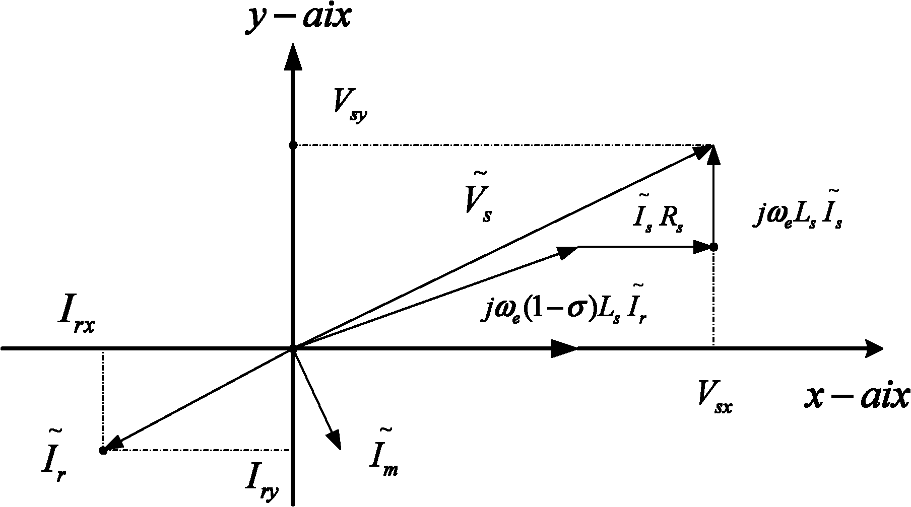
[0066] Specific implementation mode three: the following combination Figure 4 to Figure 11 Describe this embodiment, this embodiment is the further description to Embodiment 2, the calculation formula of the base 2 power method of described Fast Fourier Transform FFT is:

[0067] x L ( K L ) = x L - 1 ( K L ) + x L - 1 ...


PUM


Abstract

The invention relates to a rotor-groove harmonic analysis based method for identifying the temperature of a sensorless rotor for a submersible motor, which belongs to the technical field of fundamental application combining power electronics modeling with motor control and solves the problem that the temperature identification of a rotor for a submersible motor greatly depends on motor parameters in the prior art. The method comprises the following steps of: firstly, acquiring the three-phase stator voltage and the three-phase stator current of the submersible motor; secondly, respectively processing the three-phase stator voltage and the three-phase stator current through a signal conditioning circuit, wherein processed signals are used as original stator current input signals and original stator voltage input signals; thirdly, converting frequency spectra of the original stator current input signals through a DSP (Digital Signal Processor), so as to obtain the harmonic frequency fseh of the rotor and further obtain the rotary speed s of the rotor; and fourthly, simultaneously calculating the inductance of the motor through an original one-phase stator voltage input signal vector and an original one-phase stator current input signal vector, so as to further obtain the temperature value of the rotor. The method provided by the invention is suitable for measuring the temperature of the rotor for the submersible motor.

Description

technical field [0001] The invention relates to a sensorless rotor temperature identification method for a submersible motor based on harmonic analysis of rotor slots, and belongs to the field of application basic technology combining power electronic modeling and motor control. Background technique [0002] Submersible motors generally work at a depth of 1,000 to 3,500 meters underground, and are connected to the ground power supply through long cables. Since the working space of the submersible motor is extremely narrow and the heat dissipation effect is very poor, the thermal protection of the motor is particularly important. In order to reliably implement a thermal protection scheme for the submersible motor, it is necessary to remotely monitor the temperature of the motor. Provide reliable data for the implementation of thermal protection schemes. [0003] In the process of testing the temperature of the submersible motor, the measurement of the rotational speed is a v...

Claims


Application Information

Patent Timeline
IPC IPC(8): G01K7/00G06F17/14G06F17/16
Inventor 王立国徐殿国郝宏海张凤娜夏禹李临春吕琳琳
Owner HARBIN INST OF TECH
Learn More