
Iron and steel continuous casting equipment oriented method and device for forecasting faults

A technology for steel continuous casting and fault prediction, which is applied in the direction of measuring devices, machine/structural component testing, special data processing applications, etc. It can solve equipment management and production management services, state information with many parameters, and fault prediction cannot be made, etc. problem, achieve the effect of reducing the trouble of wiring and reducing the application cost

Inactive Publication Date: 2011-05-25
TONGJI UNIV
View PDF9 Cites 44 Cited by
  • Summary
  • Abstract
  • Description
  • Claims
  • Application Information

AI Technical Summary

Problems solved by technology

For iron and steel continuous casting equipment, there are many state information parameters of the equipment. The existing invention only analyzes the vibration signal of the rotating machinery, and cannot fully grasp the state information of the equipment, nor can it make a more comprehensive fault prediction.
On the other hand, for many complex and harsh production environments, it is very difficult to collect equipment status data and make real-time predictions through wired methods
Furthermore, the existing invention uses the collected data only for fault diagnosis and prediction, but does not store and upload the data as equipment management and production management services

Method used


Image

  • Iron and steel continuous casting equipment oriented method and device for forecasting faults
  • Iron and steel continuous casting equipment oriented method and device for forecasting faults
  • Iron and steel continuous casting equipment oriented method and device for forecasting faults

Examples


Embodiment 1

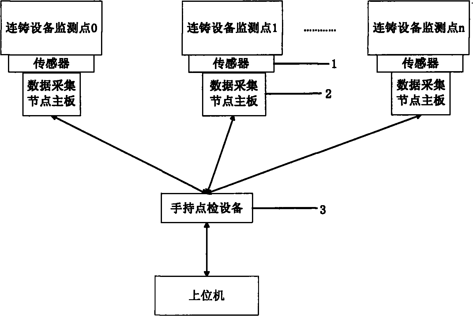
[0040] Such as figure 1 As shown, a device oriented to a fault prediction method for steel continuous casting equipment consists of sensors 1 (acceleration vibration sensor, thermocouple temperature sensor, electromagnetic flow sensor, electromagnetic pressure sensor and eddy current sensor) that collect various state parameters of continuous casting equipment device), data acquisition node main board 2 and hand-held inspection equipment 3. The acceleration vibration sensor monitors the vibration displacement of the rotating machinery bearing, the thermocouple temperature sensor monitors the temperature of different points of the equipment, the electromagnetic flow sensor monitors the flow of cooling water, the electromagnetic pressure sensor monitors the oil and gas lubrication terminal pressure, and the eddy current sensor monitors the motor current. The voltage signals corresponding to the output of each sensor are connected to the main board 2 of the data acquisition node;...


PUM


Abstract

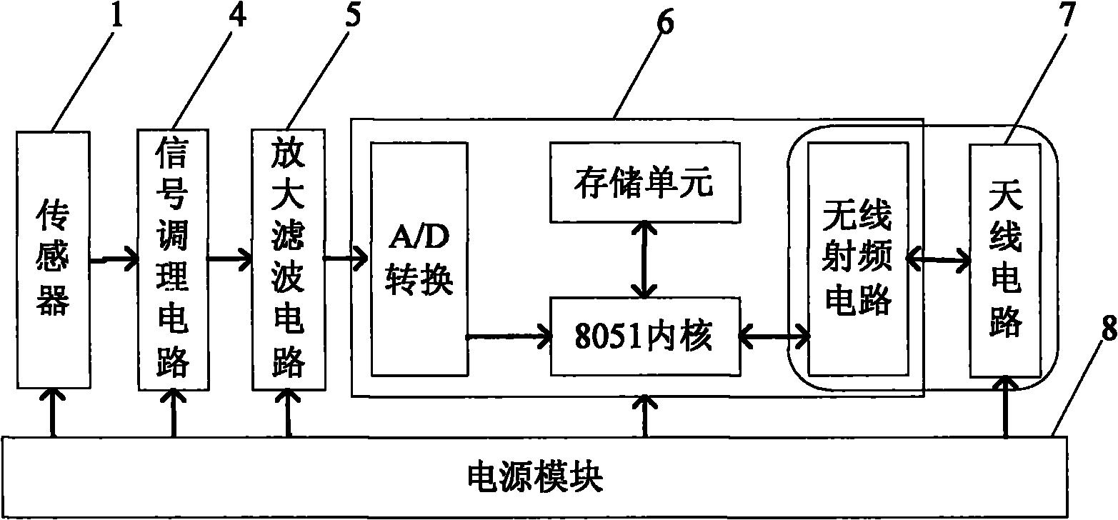
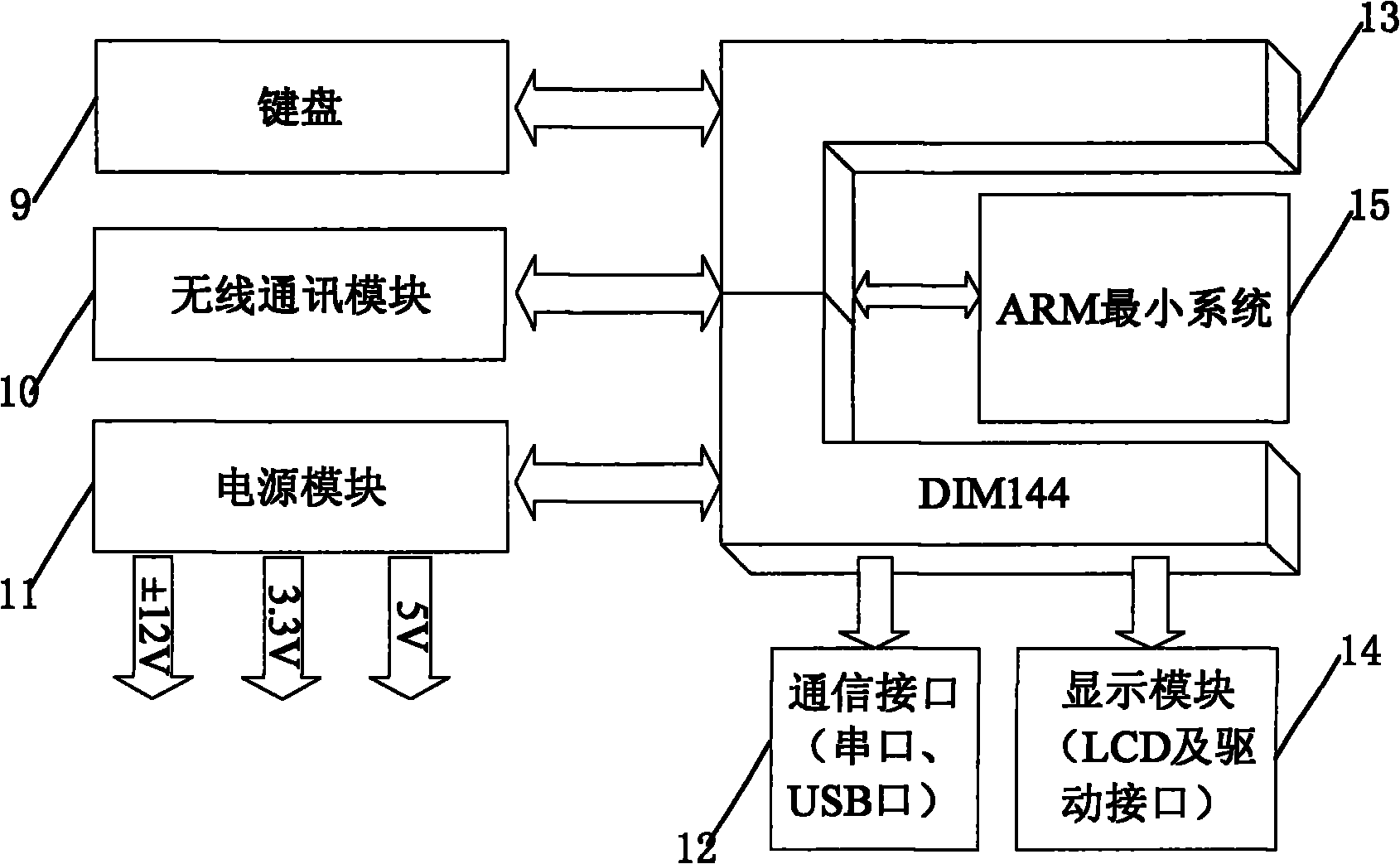
The invention relates to an iron and steel continuous casting equipment oriented method and device for forecasting faults. The device is characterized in that sensors installed on iron and steel continuous casting equipment are used for acquiring real-time status parameters of the equipment; the signals are processed by signal conditioning circuits, amplifying and filtering circuits and A / D conversion modules of data acquisition nodes and the data are sent to handheld spot inspection equipment via radio circuits supporting the Zigbee protocols; the handheld spot inspection equipment receives and analyzes the data; eigenvectors of equipment status data are constructed based on decomposition and construction carried out by wavelet packets, the eigenvectors are used as samples, support vector data description is utilized to train a single-value classifier, and the domesticated classifier is utilized to compute the health index of the equipment and describe the deterioration curve of the equipment so as to further forecast the residual service life of the equipment; the data acquisition node main boards comprise the sensors, the signal conditioning circuits, the amplifying and filtering circuits, single chips and antenna circuits; and the handheld spot inspection equipment comprises a radio communication module, an advanced RISC machines (ARM) minimum system, a keyboard and a display module. The method and the device have the beneficial effects of adopting the radio communication mode and abandoning the traditional industrial buses, being applied in the harsh production equipment such as iron and steel continuous casting lines, reducing the trouble of arranging lines and lowering the application cost.

Description

technical field [0001] The invention belongs to the technical field of fault diagnosis and prediction of mechanical equipment, and in particular relates to a fault prediction method and device for iron and steel continuous casting equipment. Background technique [0002] The demand for equipment maintenance management services in the domestic manufacturing industry continues to rise. There is an urgent need to develop an MRO support system for large-scale equipment, to provide comprehensive digital solutions and information integration technologies for equipment manufacturers, equipment users and equipment service companies, and to promote the leapfrog development of the manufacturing service industry. At present, domestic iron and steel continuous casting production lines still adopt the maintenance mode of after-event maintenance and planned maintenance. The maintenance costs are high, and unplanned shutdowns of equipment are prone to occur, causing huge losses. Tradition...

Claims


Application Information

Patent Timeline
IPC IPC(8): G01M99/00G06F19/00
Inventor 刘敏严隽薇尹九波
Owner TONGJI UNIV
Learn More