
Light-emitting device and lighting appliance

A light-emitting device and light-emitting element technology, which is applied to semiconductor devices of light-emitting elements, lighting devices, lighting and heating equipment, etc., can solve the problems of insulation core damage, warping, and poor quality, and achieve stable life, suppress warping, The effect of stable quality

Inactive Publication Date: 2011-05-25
TOSHIBA LIGHTING & TECH CORP
View PDF4 Cites 7 Cited by
  • Summary
  • Abstract
  • Description
  • Claims
  • Application Information

AI Technical Summary

Problems solved by technology

However, it is not good in the following two points
First, when the torque (torque) used to fasten the screws is too strong, the insulating core may be damaged because it is made of ceramics
Second, the linear expansion coefficient of the second metal layer of the DCB substrate and the heat sink is larger than that of the DCB substrate, so if the temperature of the DCB substrate and the heat sink rises, the DCB substrate may warp
At this time, the stress may concentrate on the screw holes and cause damage to the insulating core

Method used


Image

  • Light-emitting device and lighting appliance
  • Light-emitting device and lighting appliance
  • Light-emitting device and lighting appliance

Examples


Embodiment Construction

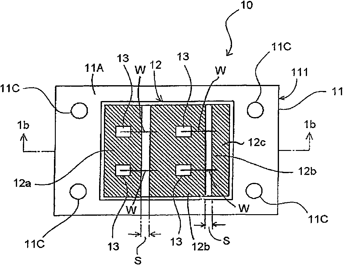
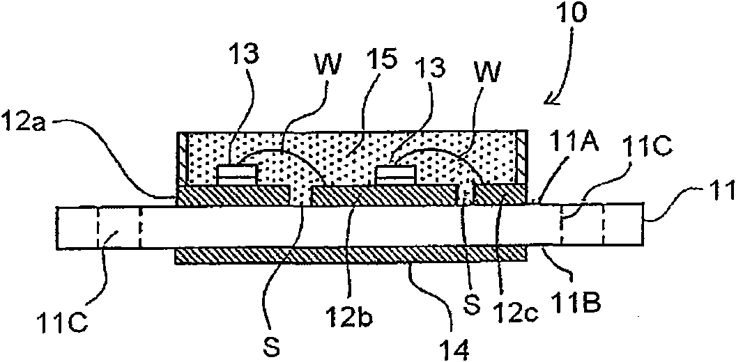
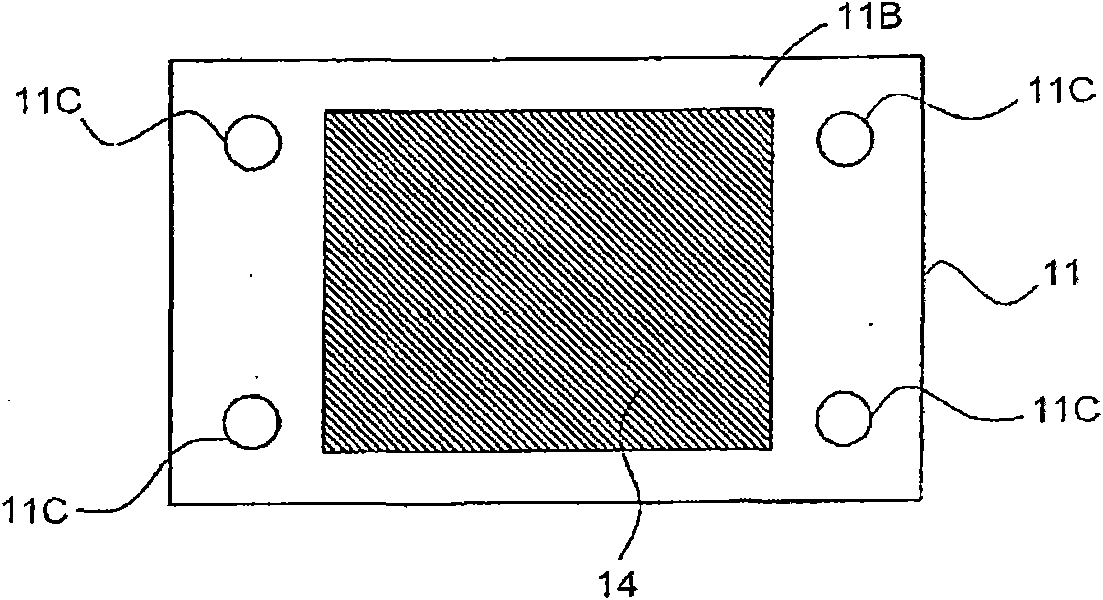
[0081] A light emitting device according to one embodiment includes an insulating base, a front metal member, a semiconductor light emitting element, and a rear metal member. The insulating base is made of ceramics. The front metal component is divided and arranged on the surface of the insulating base. The semiconductor light emitting element is installed on the front metal component. The rear metal member is formed on the rear surface of the insulating base with the same or thinner thickness as that of the front metal member. The volume of the back metal member is 50% or more compared with the volume of the front metal member.

[0082] The insulating base, the front metal component and the back metal component constitute the substrate. Examples of the substrate include a DCB (Direct Copper Bonding) substrate, a Direct Brazing Aluminum (DBA) substrate, an Active Metal Brazed Copper (AMC) substrate, and the like. The DCB substrate is formed by directly bonding a copper pla...


PUM


Abstract

The invention provides a light-emitting device with a ceramic substrate difficult to generate warping due to heat. The light-emitting device (10) is provided with an insulating base body (11), a right side metal component (12), a semiconductor light-emitting element (13), and a back side metal component (14). The insulating base body is ceramic. The right side metal component (2) is separated anddisposed on the surface (installation surface (11A)) of the insulating base body (11). The semiconductor light-emitting element (13) is installed on the right side metal component (12). The back sidemetal component (14) is disposed at the back side (11B) of the insulating base body (11) and is thinner than thickness of the right side metal component (12), the ratio of the volume of the back siderelative to the volume of the right side metal component (14) is higher than 50%.

Description

technical field [0001] Embodiments of the present invention relate to a light emitting device including a semiconductor light emitting element and a lighting fixture including the light emitting device. Background technique [0002] There is a light emitting device using a light emitting diode (light emitting diode, LED) chip (chip) as a semiconductor light emitting element in a light source. Since LEDs improve luminous efficiency, they are used as light sources for relatively large lighting fixtures such as offices and general lighting. Furthermore, in order to expand applications as light sources, LEDs with high conversion efficiency and high output are required. In order to realize a high-output LED, how to efficiently dissipate heat generated when the LED emits light has become an important issue. [0003] There is a light-emitting device that lights up an LED chip with an electric power of 1W or more. A substrate formed of a first metal layer, an insulating core (cor...

Claims


Application Information

Patent Timeline
IPC IPC(8): H01L25/075H01L33/48H01L33/64F21S2/00F21V29/00F21Y101/02F21K9/20F21V29/50F21V29/76F21Y115/10
CPCH01L2224/48091H01L2224/73265H01L2924/00014
Inventor 别田惣彦小川光三松田周平西村洁柴野信雄
Owner TOSHIBA LIGHTING & TECH CORP
Learn More