Strip line waveguide switch

A waveguide converter and stripline technology, applied in waveguide-type devices, electrical components, circuits, etc., can solve the problems of low efficiency, large feeder loss of microstrip array antenna, low antenna efficiency, etc., and achieve high conversion efficiency, insertion Low loss, simple and compact effect

Inactive Publication Date: 2011-05-25
10TH RES INST OF CETC
View PDF3 Cites 15 Cited by
  • Summary
  • Abstract
  • Description
  • Claims
  • Application Information

AI Technical Summary

Problems solved by technology

[0002] The biggest limitation of microstrip array antenna engineering application is the large feeder loss and l...

Method used


Image

  • Strip line waveguide switch
  • Strip line waveguide switch

Examples


Embodiment Construction

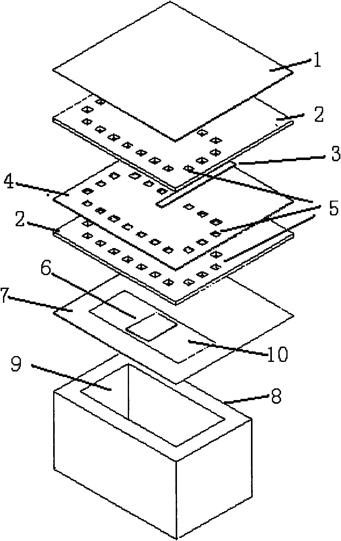
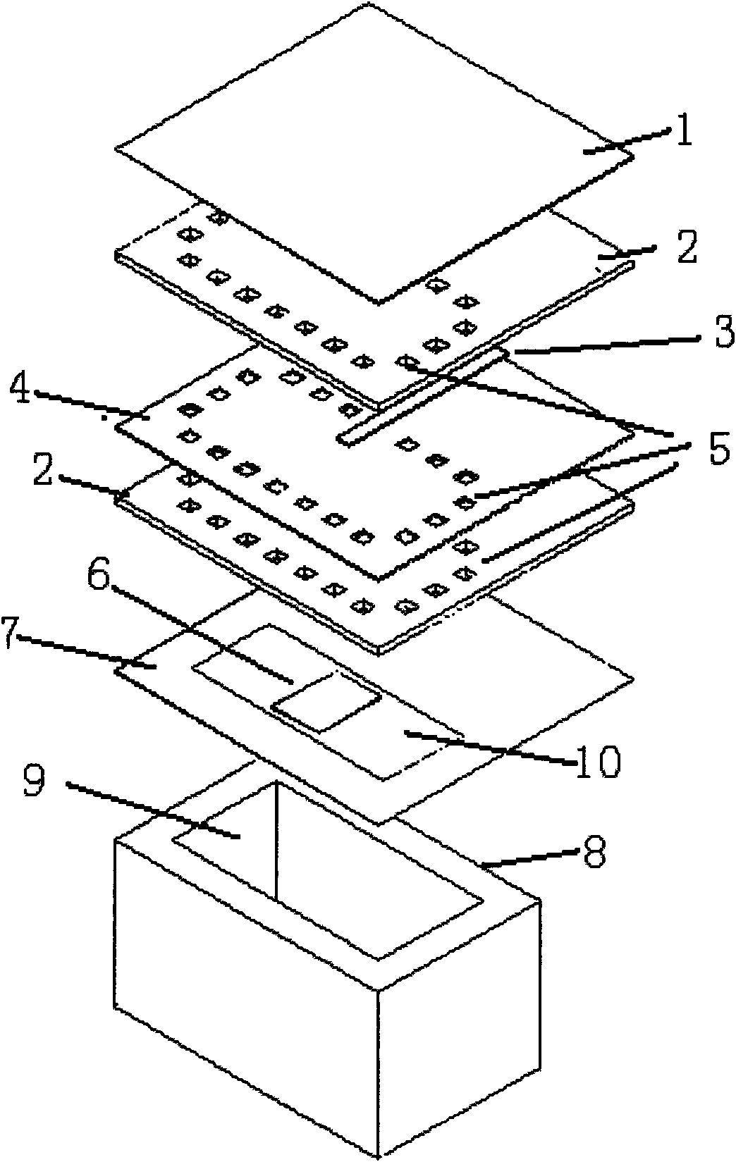
[0013] refer to figure 1 , figure 1 The stripline-waveguide converter described is a stripline-waveguide converter that can be applied in the Ka-band. The converter is a transmission line mode converter. The stripline-waveguide converter is sequentially stacked through the stripline floor 1, the microwave dielectric substrate 2, the stripline 3, the prepreg 4, the metallized via 5, the matching unit 6, the stripline floor 7, and the standard waveguide 8 combined.

[0014] The stripline floor 1 is attached to the microwave dielectric substrate 2 of the stripline 3 . The stripline subfloor 7 is attached to the microwave dielectric substrate 2 below the stripline 3 . The upper and lower microwave dielectric substrates 2 and the prepreg 4 between them are all formed with metallized via holes 5 having the same shape and size and the same arrangement and layout. The stripline 3 located on the lower end plane of the floor 1 on the stripline is formed by pressing the microwave di...


PUM


Abstract

The invention provides a strip line waveguide switch, which comprises a laminated combined body consisting of an upper strip line floor (1), a strip line (3), a matching unit (6) and a lower strip line floor (7), wherein the upper strip line floor (1) is fixedly connected onto a waveguide interface (9) of a standard waveguide (8); the strip line (3) is provided with metallized via holes (5); the upper strip line floor (1) and the lower upper strip line floor form navigation-limiting electromagnetic wave energy through the metallized via holes on the strip line (3) and the navigation-limiting electromagnetic wave energy only enters a carinal cavity transmitted by a main die of the standard waveguide, so that the energy is concentrated at the periphery of a clearance formed between two ends of the matching unit (6) and the wide side of the standard waveguide and the strip line is transmitted to the standard waveguide. The invention has the advantages of low insert loss, high conversion efficiency, simple and compact structure and low requirement for the positioning precision of the connection, can be connected by screws and is especially suitable for a Ka waveband transmission line mode.

Description

technical field [0001] The invention relates to a Ka-band transmission line mode converter. More specifically, the invention relates to a Ka-band stripline-to-waveguide converter. Background technique [0002] The biggest limitation of microstrip array antenna engineering application is the large feeder loss and low antenna efficiency. The larger the antenna aperture, the lower the efficiency, and the more obvious its disadvantages. Under the premise of acceptable antenna efficiency for the system, the forced feeding method is used to sacrifice the antenna gain in exchange for the low profile and low cost characteristics of the antenna. In order to reduce the feeder loss as much as possible and shorten the length of the feeder, the input end of the antenna is placed in the center of the array so that the total length of the feeder is the shortest. Compared with the antenna input end placed on the edge of the array, the port is placed in the center, and the feeder length i...

Claims


Application Information

Patent Timeline
IPC IPC(8): H01P1/16
Inventor 官正涛
Owner 10TH RES INST OF CETC
Why Eureka
Try Eureka