
Ball type motor with three-dimensional topology magnetic pole distribution structure

A magnetic pole, spherical technology, applied in the magnetic circuit shape/style/structure, electric components, electrical components, etc., can solve the problems of large mass and inertia, singular kinematics of joints, too small tilting moment, etc., to overcome the friction torque If it is too large, the effect of increasing the interaction force and expanding the output torque

Inactive Publication Date: 2011-05-25
BEIHANG UNIV
View PDF4 Cites 26 Cited by
  • Summary
  • Abstract
  • Description
  • Claims
  • Application Information

AI Technical Summary

Problems solved by technology

[0004] First, the inevitable elastic deformation of the transmission mechanism and the motion dead zone are the reasons for the reduction of motion accuracy;
[0005] Second, the large mass and inertia of the combined motor and accessories lead to high energy loss, and poor motion response sensitivity and rapidity limit the application range;
[0006] Third, it is easy to have kinematic singularity during the joint movement
However, in view of the problem that the tilting moment is too small in the current domestic and foreign research on spherical motors, the patent application of the present invention proposes a spherical motor with a three-dimensional topological magnetic pole distribution structure, that is: in addition to the distribution of magnetic poles along the spherical surface, the magnetic poles can also be Distributed in multiple layers in the radial direction, which can increase the output torque of the ball motor, especially the tilting moment

Method used


Image

  • Ball type motor with three-dimensional topology magnetic pole distribution structure
  • Ball type motor with three-dimensional topology magnetic pole distribution structure
  • Ball type motor with three-dimensional topology magnetic pole distribution structure

Examples


Embodiment Construction

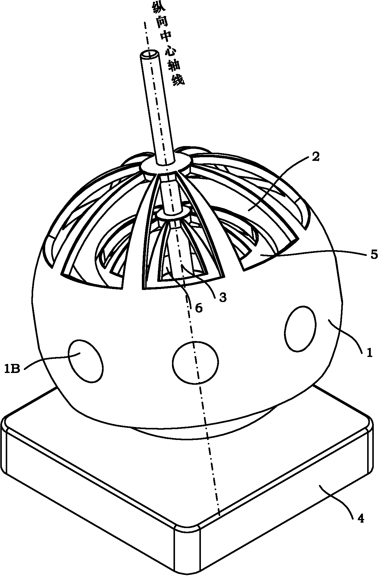
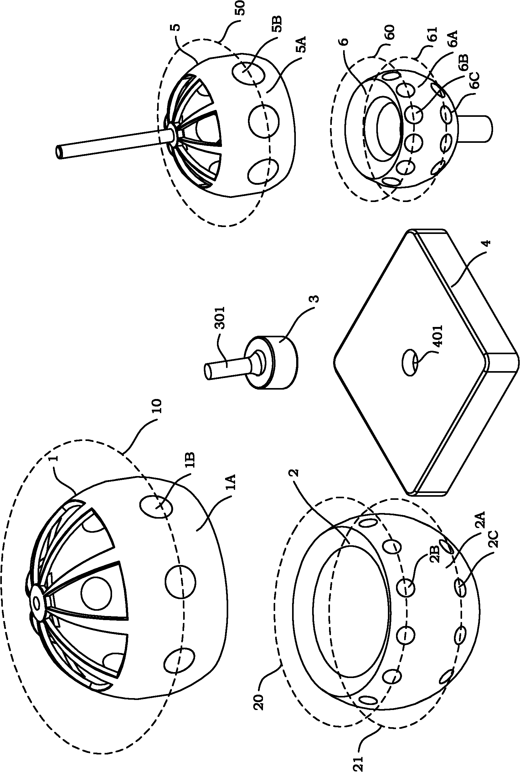
[0044] see figure 1 , Figure 1A As shown, a spherical motor with a three-dimensional topology magnetic pole distribution structure of the present invention, the spherical motor includes an outer rotor 1, an outer stator 2, a ball bearing 3, a base 4, an inner rotor 5 and an inner stator 6;

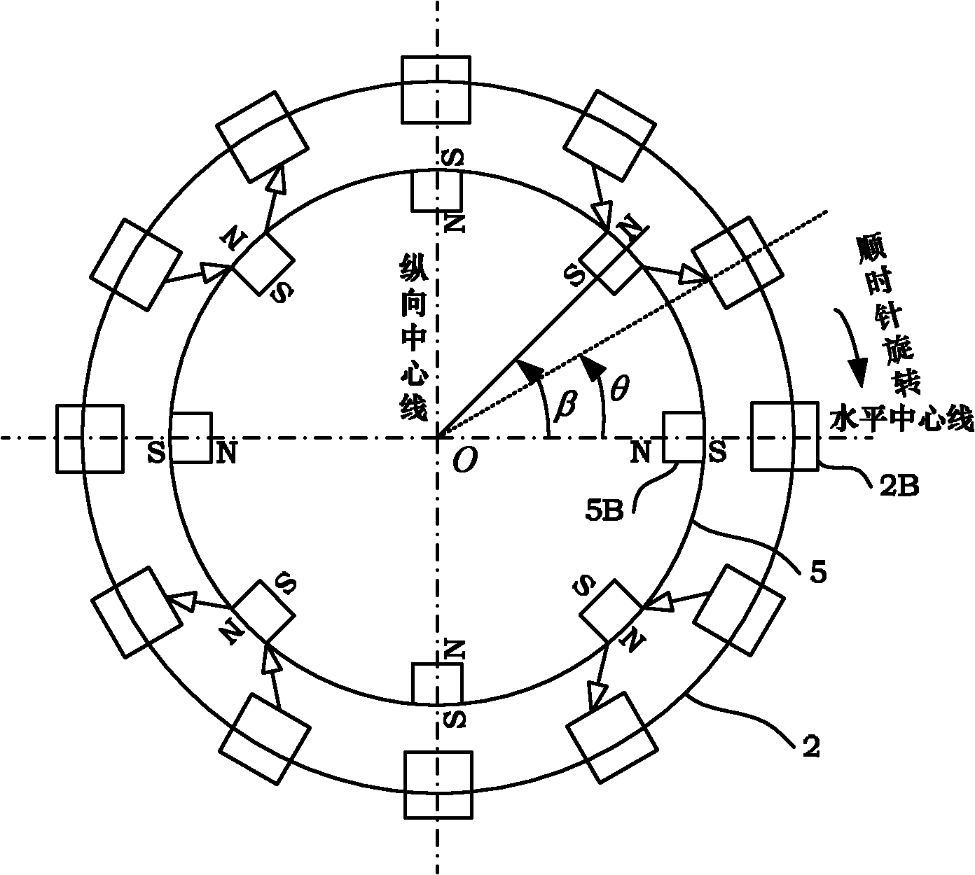
[0045] The rotor shell 1A of the outer rotor 1 (i.e., the outer rotor shell 1A) is equipped with a plurality of outer magnetic poles 1B, and the outer magnetic poles 1B are evenly distributed on the outer rotor latitude 10, and each outer magnetic pole 1B is arranged on the outer rotor latitude 10. The number satisfies β=n / 360, n represents the number of magnetic poles set, β represents the angle between the magnetic pole axis, unit °;

[0046] A plurality of inner magnetic poles 5B are installed on the rotor shell 5A of the inner rotor 5 (that is, the inner rotor shell 5A), and the inner magnetic poles 5B are evenly distributed on the inner rotor latitude 50, and the inner magnetic pole...


PUM


Abstract

The invention discloses a ball type motor with a three-dimensional topology magnetic pole distribution structure The ball type motor comprises an outer rotor (1), an outer stator (2), a ball bearing (3), a base (4), an inner rotor (5) and an inner stator (6), wherein the rotor and the stator are sleeved with each other; the ball bearing (3) is installed in the inner stator (6); the inner rotor (5) is sleeved on the external part of the inner stator (6); the outer stator (2) is sleeved on the external part of the inner rotor (5); and the outer rotor (1) is sleeved on the external part of the outer stator (2). The electromagnetic force driving is adopted for the ball type motor disclosed by the invention, besides magnetic poles and coil magnetic poles are distributed along a spherical surface, and also can be distributed along the radial direction, thus the magnetic field intensity of a coil magnetic pole region is increased greatly, simultaneously the interaction force between the magnetic poles is improved, not only can the continuous rotation space with spatial three degrees of freedom of the ball motor rotor can be realized, but also the output torque, especially the tilting moment, of the ball motor is improved effectively.

Description

technical field [0001] The invention relates to a spherical motor, more particularly, to a spherical motor with a three-dimensional topology magnetic pole distribution structure. In addition to being distributed along the spherical surface, the magnetic poles in the spherical motor can also be distributed in multiple layers in the radial direction, so that the output torque of the spherical motor can be increased, especially the performance of the tilting torque is significantly improved. Background technique [0002] Bionics is one of the important foundations for the development of robotics. The human arm has seven degrees of freedom, that is, the shoulder and wrist are three-degree-of-freedom ball joints, and the elbow is a single-degree-of-freedom rotary joint. The human arm not only has a large working space, a good carrying capacity, but also outstanding flexibility. The ball motor can realize the continuous rotation of three degrees of freedom in space, so the devel...

Claims


Application Information

Patent Timeline
IPC IPC(8): H02K16/00H02K1/22H02K1/12H02K5/173H02K1/27H02K1/14
Inventor 严亮张良兰华
Owner BEIHANG UNIV
Learn More