Method for producing a component through selective laser melting and process chamber suitable therefor

A laser melting and selective technology, applied in additive manufacturing, manufacturing tools, laser welding equipment, etc., can solve the problems of poor mechanical properties of catalytic materials

Inactive Publication Date: 2011-05-25
SIEMENS AG
View PDF10 Cites 49 Cited by
  • Summary
  • Abstract
  • Description
  • Claims
  • Application Information

AI Technical Summary

Problems solved by technology

Of course, it must be taken into account in this approach that the mechanical properties of catalytic materials are often inferior t

Method used


Image

  • Method for producing a component through selective laser melting and process chamber suitable therefor
  • Method for producing a component through selective laser melting and process chamber suitable therefor
  • Method for producing a component through selective laser melting and process chamber suitable therefor

Examples


Embodiment Construction

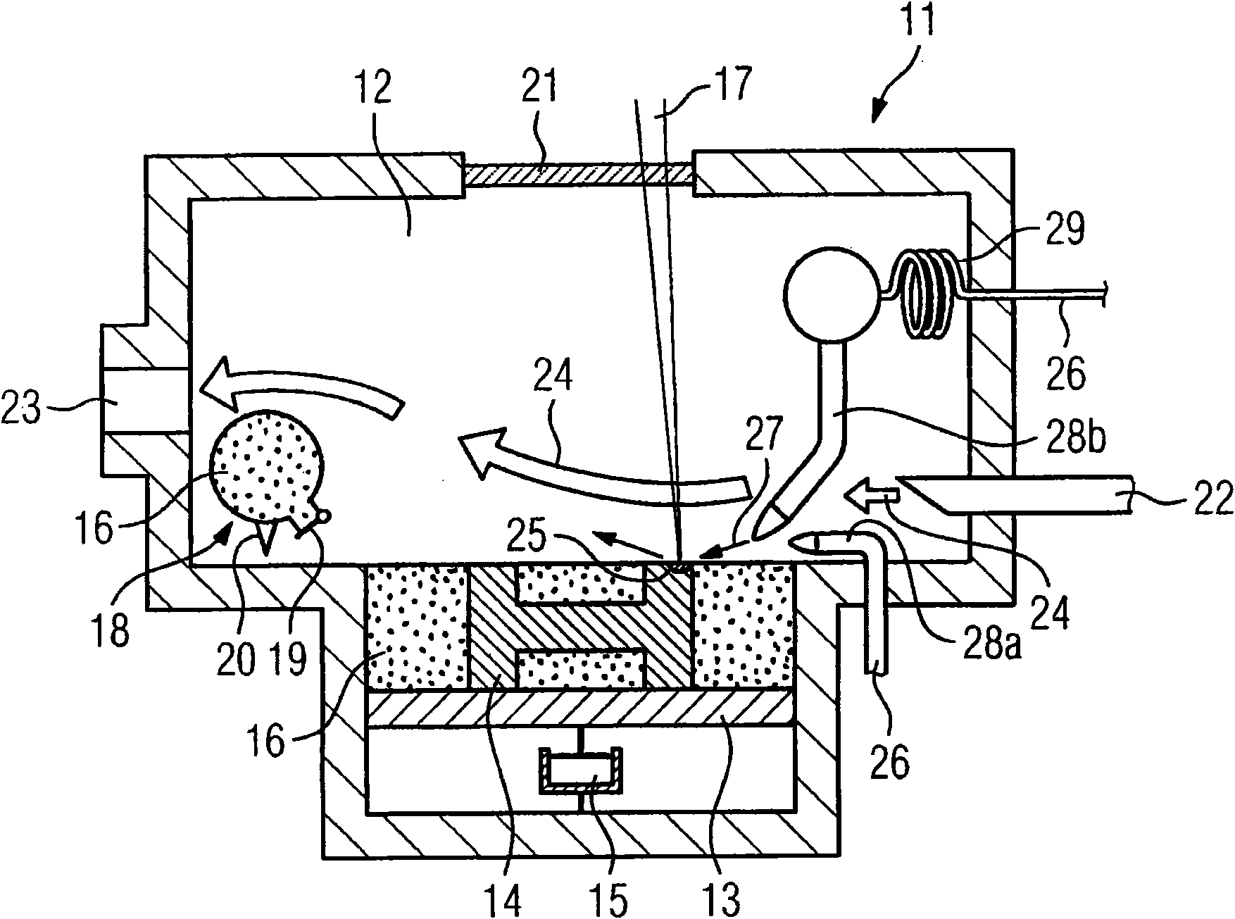
[0023] figure 1 The operating room 11 shown has an operating chamber 12 in which a receiving table 13 for a component 14 to be produced is arranged. The receiving table can be lowered by means of the actuator 15, so that the component 14 can be produced in a storage tank of component raw material powder 16, at this time, the receiving table 13 is always lowered after one layer of the component 14 has been produced by means of the laser beam 17 The amount of thickness of the layer. A moving storage tank 18 with a metering valve 19 and a scraper 20 can be moved over the storage tank in a manner not shown in detail, so that after the receiving table 13 has been lowered, it can be applied on the layer where the component 14 has been made. Another layer of powder.

[0024] The laser is installed outside the operating room 11, not further shown in the figure. The operating room has a window 21 through which the laser beam enters the operating room. Furthermore, the operating cha...


PUM


Abstract

The invention relates to a method for producing a component through selective laser melting and to a process chamber (11) for carrying out the method. According to the invention, the selective laser melting by way of a laser (17) is also used for producing coating areas (25) of the component (14) being produced, said coating areas having a composition that differs from the composition of the powder. This is accomplished by intermittently introducing a reactive gas (27) that reacts with the powder material or that produces a material on the component (14) from precursors present in the reactive gas. In the process chamber according to the invention, an additional feed line (28a, 28b) is provided for introducing reactive gas, said feed line permitting the feeding of the reactive gas if possible close to the laser (17).

Description

technical field [0001] The invention relates to a method for producing components by selective laser melting, wherein the components are produced in layers from powder by melting raw material particles by means of a laser beam. Background technique [0002] A method of the type mentioned in the introduction is known, for example, from DE 102 23 796 C1. It can, for example, be produced by selective laser melting into complex three-dimensional structures which have a large surface compared to the amount of material consumed. These structures can also be used as catalysts, for which they are obtained from catalytic materials by means of laser melting. Of course, in this method it must be taken into account that the mechanical properties of catalytic materials are often inferior to those of conventional structural materials, so that this must be taken into account, for example, when designing the wall thickness. Contents of the invention [0003] The technical problem to be ...

Claims


Application Information

Patent Timeline
IPC IPC(8): B23K26/34B22F3/105
CPCB23K26/34B23K26/322B22F3/1055B22F2998/00B22F2003/1056B23K35/38B23K35/383B23K35/0244B23K26/32B23K2103/14Y02P10/25B22F10/28B22F10/32B22F12/70B22F10/50B22F3/003
Inventor 克里斯琴·多伊斯文·派里茨尤维·派里茨马丁·谢弗
Owner SIEMENS AG
Why Eureka
Try Eureka