Centrifugal extractor

A technology for extractors and flow guides, which is applied in the field of liquid-liquid two-phase centrifugal extractors, and can solve problems such as insufficient mixing and separation of light and heavy phases, limited drum speed, and difficulty in achieving extraction and separation effects, etc.

Active Publication Date: 2011-06-01
北京萃取应用技术研究所
View PDF7 Cites 14 Cited by
  • Summary
  • Abstract
  • Description
  • Claims
  • Application Information

AI Technical Summary

Problems solved by technology

[0003] In the above-mentioned existing centrifugal extractor, since the main shaft is directly connected with the drum, when the main shaft drives the drum at the end to rotate at a high speed, the centrifugal extractor will vibrate. The rotating speed of the drum makes the mixing and separation effect of the light and heavy phase not good en...

Method used


Image

  • Centrifugal extractor
  • Centrifugal extractor
  • Centrifugal extractor

Examples


Embodiment Construction

[0030] Specific embodiments of the present invention will be described in detail below in conjunction with the accompanying drawings. It should be understood that the specific embodiments described here are only used to illustrate and explain the present invention, and are not intended to limit the present invention.

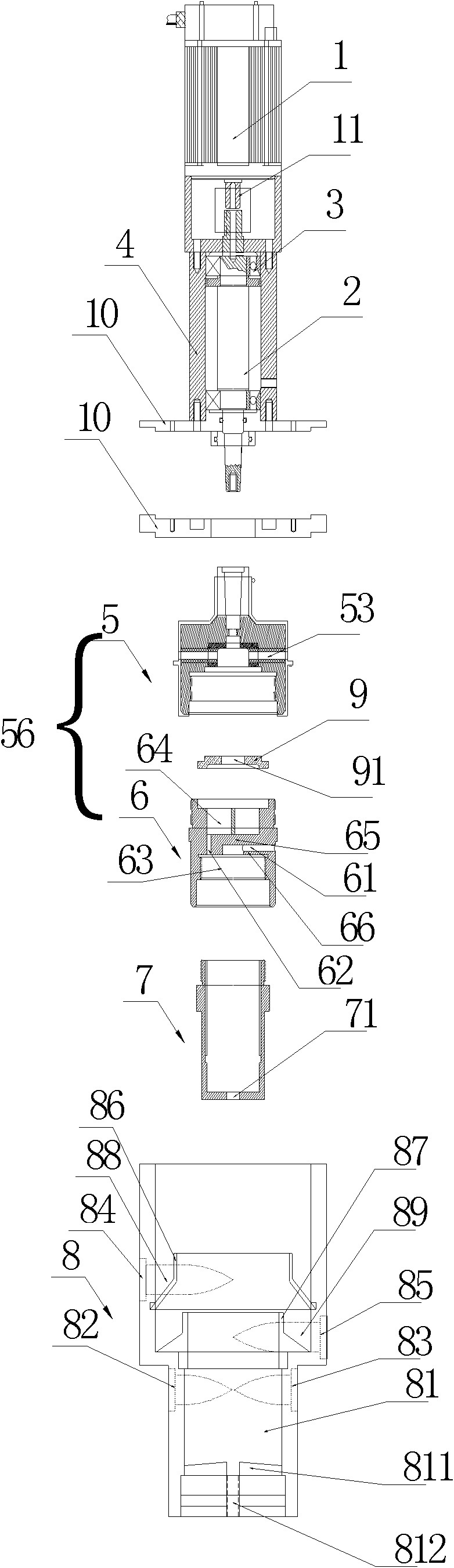
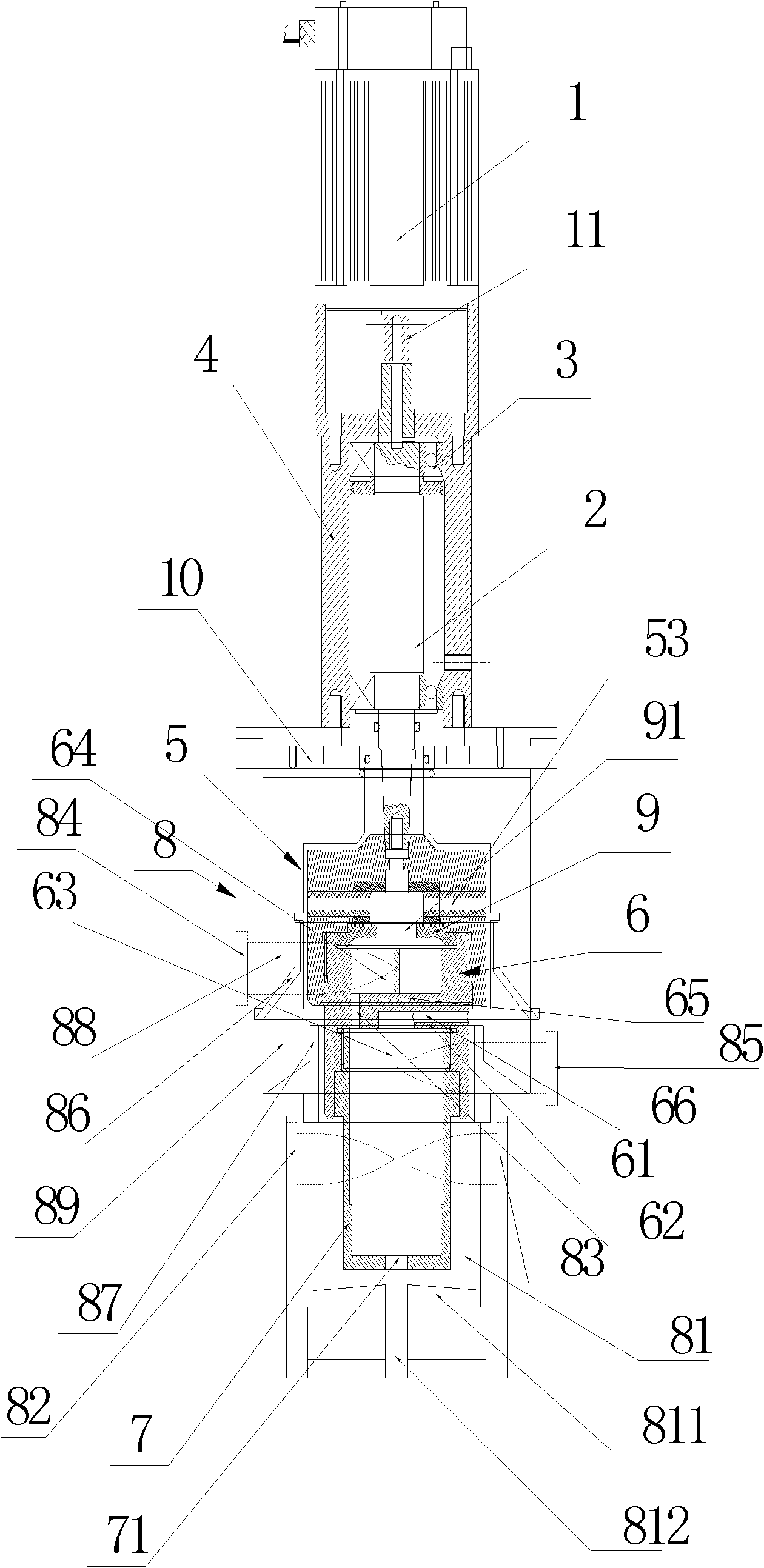
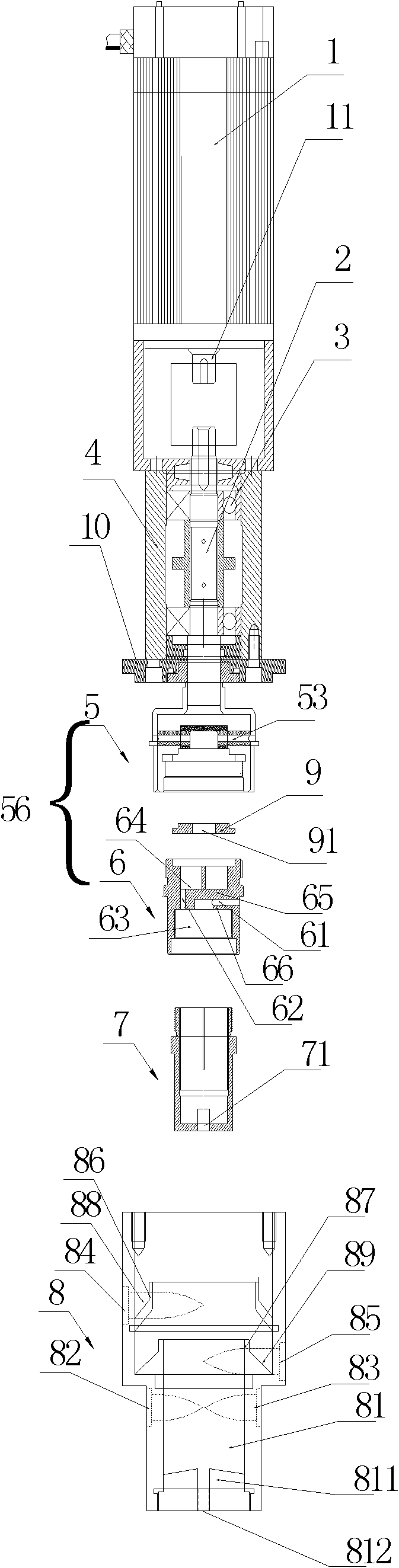
[0031] Such as Figure 1 to Figure 4 As shown, the present invention improves a kind of centrifugal extractor, and this centrifugal extractor comprises motor 1, main shaft 2, guide member 56, rotating drum 7 and shell 8, and one end of described main shaft 2 is connected with the output shaft of described motor 1 11 connection (for example, it can be connected by a coupling), the drum 7 is used to separate the light phase and the heavy phase entering the drum under the action of centrifugal force, and the guide member 56 is used to guide the 7 The separated light phase and heavy phase are respectively discharged through their respective paths, wherein the other...


PUM


Abstract

The invention discloses a centrifugal extractor. The centrifugal extractor comprises a motor (1), a spindle (2), a flow guide part (56), a rotating drum (7) and a shell (8), wherein one end of the spindle (2) is connected with an output shaft (11) of the motor (1), and the other end of the spindle (2) is fixedly connected with the flow guide part (56); and the flow guide part (56) is fixedly connected with the rotating drum (7) and is positioned in the shell (8). Through the technical scheme, the rotating drum is indirectly connected to the spindle through the flow guide part and is indirectly driven to rotate by the spindle, so that when the spindle drives the rotating drum to rotate through the flow guide part, the extractor is not obviously vibrated even if rotating speed is high; therefore, ideal extraction and separation effects also can be achieved under the condition that the ratio difference of two-phase flow is large or the density difference of two phases is small.

Description

technical field [0001] The invention relates to a centrifugal extractor, in particular to a liquid-liquid two-phase centrifugal extractor. Background technique [0002] As an efficient and fast extraction technology, centrifugal extraction technology is widely used in fields such as hydrometallurgy, medicine, wastewater treatment, fine chemical industry, food, plant component extraction, and military affairs. The existing centrifugal extractor mainly includes a motor, a main shaft, a bearing, a bearing seat, a guide part, a drum and a casing, the main shaft is connected to the bearing seat through the bearing, and one end of the main shaft is connected to the motor The output shaft of the main shaft is connected, the other end of the main shaft is fixedly connected with the drum, and the guide part and the shell constitute the heavy phase inlet, the light phase inlet, the heavy phase outlet, the light phase outlet, the mixing chamber, the heavy phase guide flow path and lig...

Claims


Application Information

Patent Timeline
IPC IPC(8): B01D11/04
Inventor 玄浩
Owner 北京萃取应用技术研究所
Why Eureka
Try Eureka