Printing unit of direct rotary machine

A technology of printing unit and printing machine, which is applied in the direction of rotary printing machine, printing machine, general parts of printing machinery, etc. It can solve the problems of affecting printing quality, uneven surface closeness, uneven ink distribution, etc., and achieve clutch operation Convenient and reliable, improve printing quality, avoid the effect of dark and light color difference

Inactive Publication Date: 2012-02-29
东莞市中崎机械有限公司
View PDF0 Cites 0 Cited by
  • Summary
  • Abstract
  • Description
  • Claims
  • Application Information

AI Technical Summary

Problems solved by technology

[0003] Since the ink is transferred to the ink separation roller through a single channel, and then divided to two backing rollers by the ink separation roller, this kind of ink transfer system is often due to wear during use, installation errors between the ink separation roller and each backing roller, etc. Factors cause the surface of the ink separation roller and the form roller to be in different degrees of closeness, which can easily cause uneven ink distribution, resulting in layered differences in the thickness of the printing ink layer, and printing depth and light color difference, which affects printing quality.
[0004] In the printing unit with the above structure, in order to achieve the purpose of the ink separating roller to transfer the ink to the two form rollers, the ink separating roller needs to be tangent to the two form rollers, so the ink separating roller has a large diameter and a large weight. This brings difficulty to the clutch of the form roller and the printing cylinder
In the existing clutch system of the printing unit, the clutching of the form roller and the printing plate cylinder is realized mainly by means of the eccentric wheels respectively installed under the mounting seats of the two form rollers. The installation seat, and then push the ink transfer system, so as to realize the clutch between the plate roller and the printing plate cylinder. During the clutch process, because the eccentric wheel needs to push the entire ink transfer system, the power of the clutch system is large and the energy consumption is high; and in order to ensure the two The smooth clutch between the plate roller and the printing plate cylinder often requires the synchronous rotation of two eccentric wheels, which makes the structure of the clutch system complex, and the operation of adjusting the synchronous rotation of the eccentric wheels is cumbersome

Method used


Image

  • Printing unit of direct rotary machine
  • Printing unit of direct rotary machine
  • Printing unit of direct rotary machine

Examples


Embodiment Construction

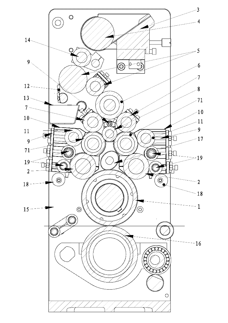
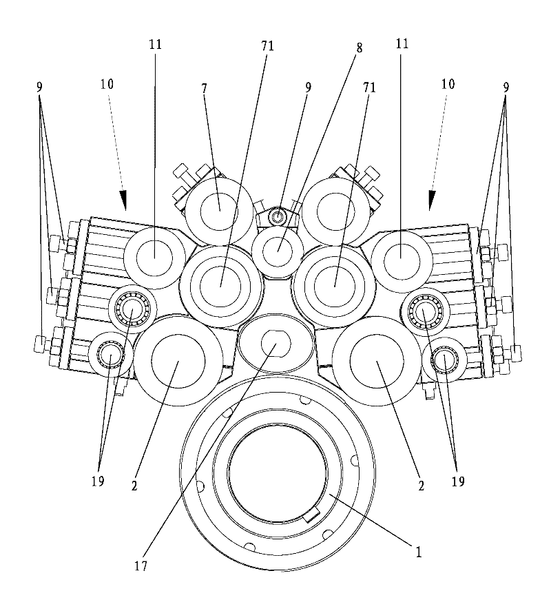
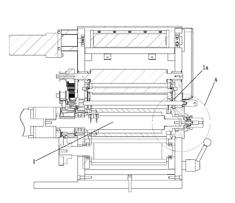
[0036] The present invention will be further explained below in conjunction with the drawings, see figure 1 with figure 2 As shown, this is the preferred embodiment of the present invention.

[0037] A printing unit of a rotary printing press includes a housing 15 and an ink supply system, an ink transfer system and a printing roller pair arranged in the housing 15. The printing roller pair includes a printing plate cylinder 1 and a printing roller The ink transfer system includes two plate rollers 2 tangent to the printing plate cylinder 1, and an ink supply roller 4 arranged at the outlet of the ink fountain 3 of the ink supply system. The ink supply roller 4 is connected below There is an ink ejection roller 14, the ink ejection roller 14 is connected to an ink transfer roller group 5, and the end of the ink transfer roller group 5 away from the ink ejection roller 14 is connected to an ink separation roller 6; the ink separation roller 6 and Each ink transfer branch is provi...


PUM


Abstract

The invention discloses a printing unit of a direct rotary machine, which comprises an ink supply system, an ink delivery system and a printing roller pair, wherein the printing roller pair comprises a printing plate cylinder and a printing roller; the ink delivery system comprises an ink distribution roller, an ink delivery group, an ink separation roller, and two form ink rollers which are tangential with the printing plate cylinder respectively; an ink delivery shunt is arranged between the ink separation roller and each form ink roller; a shunt ink delivery roller of each ink delivery shunt contacting the form ink roller is a terminal shunt ink delivery roller; each form ink roller and the corresponding terminal shunt ink delivery roller are pivoted in a roller seat; the axis of the terminal shunt ink delivery roller corresponding to the roller seat can be pivotally arranged a shell; a clutch cam capable of pressing against the roller seats is arranged between the two roller seats; ink is delivered to the form ink rollers through the ink delivery shunts and is delivered uniformly, so depth color differences of outgoing line printing are avoided and the printing quality is improved; and the clutching of the form ink rollers and the printing plate cylinder are realized by using the clutch cam to rotate a jacking roller seat to pivot. The printing unit of the direct rotary machine is simple in structure and convenient and reliable in clutching operation.

Description

Technical field [0001] The invention relates to the technical field of rotary printing machines, and in particular to a printing unit of a rotary printing machine. Background technique [0002] The printing unit of a rotary printer is generally composed of an ink supply system, an ink transfer system, a printing roller pair and a clutch system. In the printing unit of the existing rotary printing machine, the ink transfer system adopts a structure in which a single-path ink distributing double leaning against a plate roller supplies ink to the printing plate. Specifically, its structure includes a housing, a printing plate cylinder and an ink fountain are arranged in the housing, and an ink transfer system is arranged between the printing plate cylinder and the ink fountain. The ink transfer system includes two tangents to the printing plate cylinder. There are two plate-retaining rollers, the two plate-retaining rollers are both tangent to an ink separator roller, and several i...

Claims


Application Information

Patent Timeline
Patent Type & Authority Patents(China)
IPC IPC(8): B41F13/00B41F31/34B41F35/04
Inventor 程刚
Owner 东莞市中崎机械有限公司
Why Eureka
Try Eureka