Self-injection locking light source and light source self-injection locking method and system

A self-injection locking, light source technology, applied in the field of optical communication, can solve the problems of high cost and low modulation rate, and achieve the effect of reducing cost and simple device and system solution

Active Publication Date: 2011-06-01
HUAWEI TECH CO LTD
View PDF7 Cites 30 Cited by
  • Summary
  • Abstract
  • Description
  • Claims
  • Application Information

AI Technical Summary

Problems solved by technology

[0006] However, the current self-injection locking or self-seed colorless light source technologies proposed...

Method used


Image

  • Self-injection locking light source and light source self-injection locking method and system
  • Self-injection locking light source and light source self-injection locking method and system
  • Self-injection locking light source and light source self-injection locking method and system

Examples


Embodiment Construction

[0030] The following will clearly and completely describe the technical solutions in the embodiments of the present invention with reference to the accompanying drawings in the embodiments of the present invention. Obviously, the described embodiments are only some, not all, embodiments of the present invention. Based on the embodiments of the present invention, all other embodiments obtained by persons of ordinary skill in the art without creative efforts fall within the protection scope of the present invention.

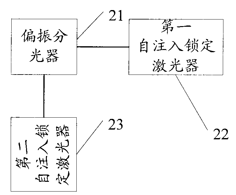
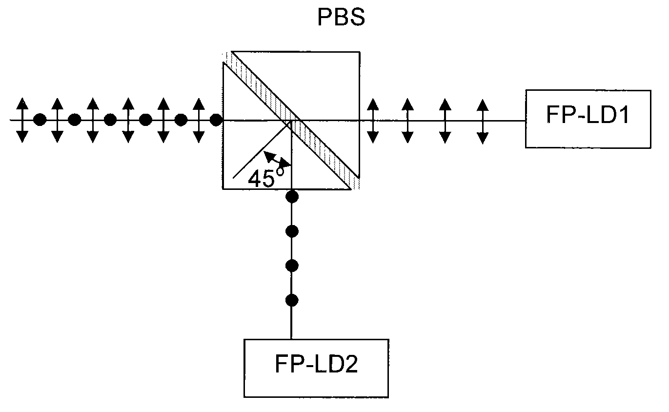
[0031] In order to solve the problem of polarization dependence of the colorless light source and reduce its implementation cost, Embodiment 1 of the present invention provides a self-injection-locked light source. like figure 2 As shown, the self-injection-locked light source according to Embodiment 1 of the present invention includes: a polarization beam splitter 21 , and a first self-injection-locked laser 22 and a second self-injection-locked laser 23 coupled ...


PUM


Abstract

The embodiment of the invention discloses a self-injection locking light source which comprises a polarized light splitter as well as a first self-injection locking laser and a second self-injection locking laser which are coupled with the polarized light splitter, wherein the polarized light splitter is used for carrying out polarized coupling on polarized light provided by the first self-injection locking laser and the second self-injection locking laser and polarized light splitting on received reflected light, and respectively providing the split light for the first self-injection locking laser and the second self-injection locking laser; and the polarization directions of the first self-injection locking laser and the second self-injection locking laser are respectively aligned to the two polarization directions of the polarized light splitter. The embodiment of the invention also provides a light source self-injection locking method and system as well as a wavelength division multiplexing passive optical network system.

Description

technical field [0001] The present invention relates to the technical field of optical communication, in particular to a self-injection locking light source, a light source self-injection locking method and system, and a wavelength division multiplexing passive optical network system. Background technique [0002] Generally speaking, a passive optical network (Passive Optical Network, PON) system includes an OLT (Optical Line Terminal, Optical Line Terminal) located in a central office, an ODN (Optical Line Terminal) for branching / coupling or multiplexing / demultiplexing Distribution Network, optical fiber distribution network) and several ONUs (Optical Network Unit, optical network unit). [0003] According to different implementation methods, passive optical networks can be divided into different types, among which WDM-PON (WaveDivision Multiplexing Passive Optical Network, wavelength division multiplexing passive optical network) is characterized by its huge bandwidth capa...

Claims


Application Information

Patent Timeline
IPC IPC(8): H04B10/18H04B10/12H04J14/02G02B27/28H04B10/272H04B10/50
CPCH04B10/50H04B10/272H04J14/0282H04J14/0227H04J14/02H04J14/0246H04J14/025H04J2014/0253H01S3/10H04B10/25
Inventor 林华枫徐之光
Owner HUAWEI TECH CO LTD
Why Eureka
Try Eureka