Hot standby redundancy network system and redundancy realization method

A technology of redundant network and implementation method, applied in the field of Ethernet communication, can solve problems such as low redundancy and reliability of real-time Ethernet, network network communication failure, and increased network failure rate.

Inactive Publication Date: 2011-06-01
SUPCON GRP +1
View PDF2 Cites 25 Cited by
  • Summary
  • Abstract
  • Description
  • Claims
  • Application Information

AI Technical Summary

Problems solved by technology

However, in a single-ring network, only one end of the cable can be faulty. When additional faults occur, the entire network will experience network communication failures.
The double-ring network can allow multiple failures in one ring network, but when two ring networks fail at the same time (such as two link failures in two rings at the same time), it will cause communication failures in the e

Method used


Image

  • Hot standby redundancy network system and redundancy realization method
  • Hot standby redundancy network system and redundancy realization method
  • Hot standby redundancy network system and redundancy realization method

Examples


Example Embodiment

[0071] Example 1:

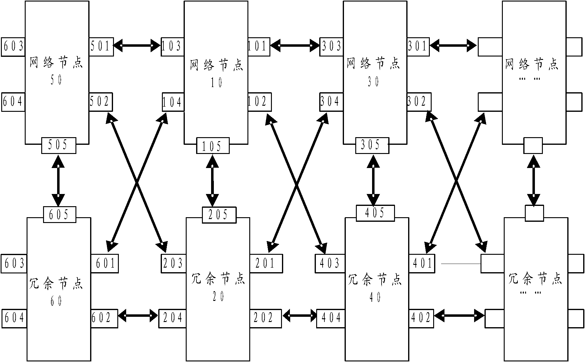
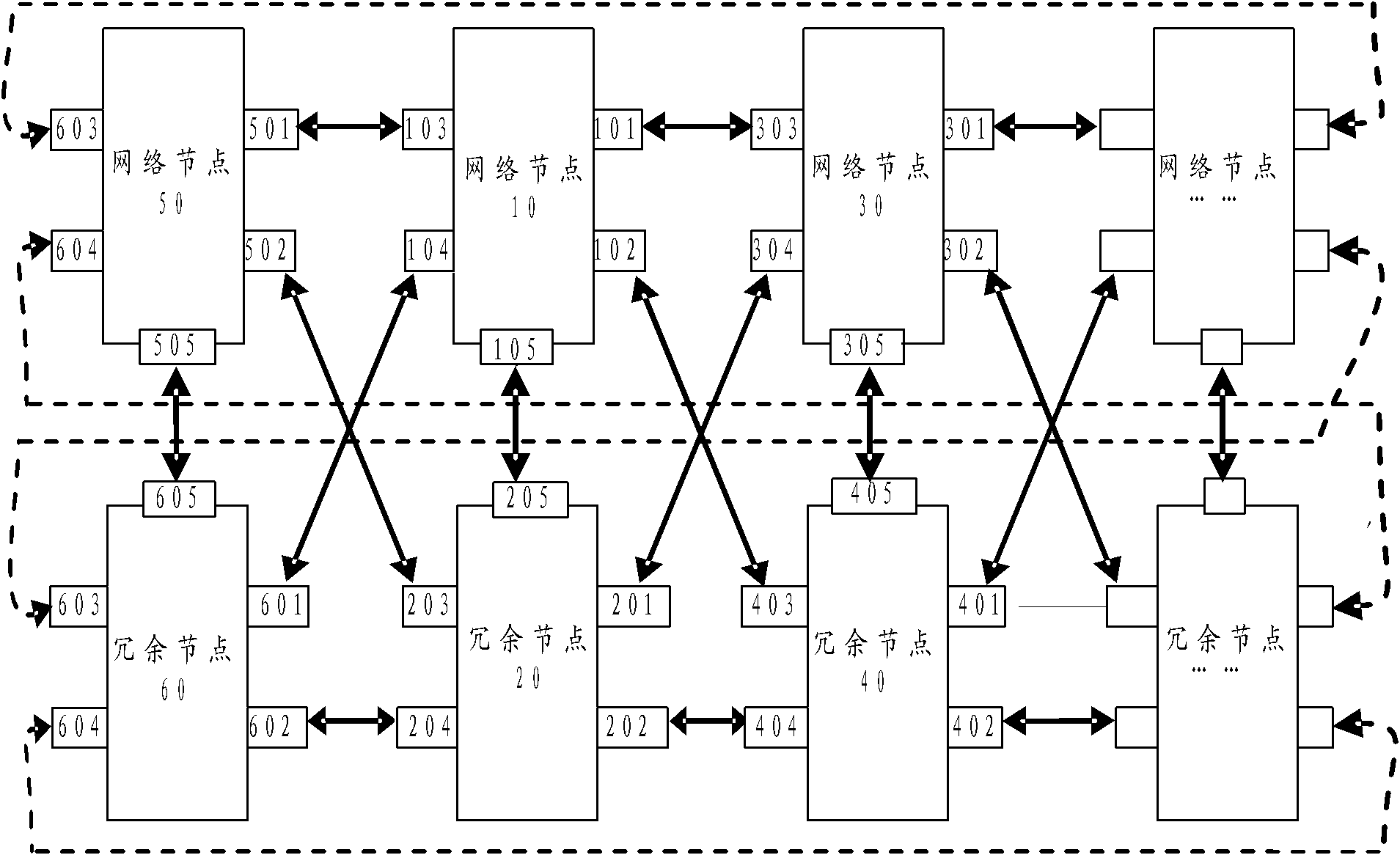
[0072] The embodiment of the present invention provides a hot standby redundant network system, which can be preferably applied to a network system composed of real-time Ethernet technology, reduces the failure rate of real-time Ethernet, and improves its redundancy and availability. like figure 1 Shown is a schematic structural diagram of the system, which includes:

[0073] A network node 10 and a redundant node 20 uniquely corresponding to the network node 10; the hot-standby redundant network system includes at least two network nodes, correspondingly, at least two redundant nodes;

[0074] The network node 10 includes a first network interface 101, a second network interface 102, a third network interface 103, a fourth network interface 104, and a switching interface 105. The physical addresses of the four network interfaces 101, 102, 103, and 104 are the same, The logical address is also the same, and the physical address and logical address of the ...

Example Embodiment

[0087] Embodiment 2:

[0088] Corresponding to the hot standby redundant network system provided by the embodiment, the embodiment also provides a redundancy implementation method suitable for the system, so as to reduce the failure rate of the real-time Ethernet and improve its redundancy and availability. The redundancy implementation method includes:

[0089] Preset the working node in the working state and the standby node in the standby state in each redundant node pair; the working node can be pre-designated by the user or the system according to the state of the node, and can also pass through the network of mutually redundant node pairs. A node and its redundant nodes compete during power-on. For example, if one node in a redundant node pair is already in a working state, the other node in the node pair will be in a standby state when powered on.

[0090] When a message needs to be sent, a working node in the system sends redundant messages to the adjacent redundant n...


PUM


Abstract

The embodiment of the invention discloses a hot standby redundancy network system and a redundancy realization method, which can be suitable for real-time Ethernet. The hot standby redundancy network system comprises at least two network nodes and redundancy nodes which are in one-to-one correspondence with the network nodes, wherein each network node and each redundancy node both comprise four network interfaces and one exchange interface, the four network interface are all provided with the same physical address and logic address, the four network interfaces make up two pairwise redundancy interface in pairs, the network nodes are connected with the corresponding redundancy nodes through the exchange interfaces to make up redundancy node pairs, and the network nodes of the adjacent redundancy node pairs are in cross connection with the redundancy nodes though the network interfaces. With the scheme, the failure rate of the real-time Ethernet is insensitive to the increase of the number of the network nodes, the data message format of the real-time Ethernet does not need to be modified, the failure rate of the real-time Etherent can be obviously reduced, and the redundant degree and the usability of the real-time Etherent can be greatly increased.

Description

Technical field: [0001] The invention relates to the technical field of Ethernet communication, in particular to a hot backup redundant network system applicable to real-time Ethernet and a method for realizing redundancy thereof. Background technique: [0002] Ethernet is the most common communication protocol standard used in today's existing local area networks. With the development of Ethernet technology, the application of Ethernet communication in the industrial field is becoming more and more extensive, and the stable operation and efficiency improvement of industrial production have put forward higher and higher requirements for the availability of real-time Ethernet. High availability is also getting more and more attention. [0003] For the high availability requirement of real-time Ethernet, the interface redundancy mechanism of single-ring network and the node redundancy mechanism of double-ring network are generally adopted at present. However, in a single-rin...

Claims


Application Information

Patent Timeline
IPC IPC(8): H04L12/24H04L1/22
Inventor 冯冬芹朱杰褚健
Owner SUPCON GRP
Why Eureka
Try Eureka