Composite material mechanical arm and manufacture method thereof

A technology of composite materials and manipulators, applied in the direction of manipulators, program-controlled manipulators, manufacturing tools, etc., can solve the problems of heavy weight and inability to meet the use requirements of precise transmission, achieve good damping performance, solve manual unloading difficulties, and resist The effect of damping properties

Inactive Publication Date: 2011-06-08
SHANGHAI COMPOSITES SCI & TECH CO LTD
View PDF0 Cites 12 Cited by
  • Summary
  • Abstract
  • Description
  • Claims
  • Application Information

AI Technical Summary

Problems solved by technology

[0004] In order to solve the problem that the existing aluminum alloy mechanical arm is heavy and unable to meet the use requirements of precise transmission, the purpose of the present invention is to provide a composite material mechanical arm

Method used


Image

  • Composite material mechanical arm and manufacture method thereof
  • Composite material mechanical arm and manufacture method thereof
  • Composite material mechanical arm and manufacture method thereof

Examples


Embodiment 1

[0021] Example 1: The structure of a composite material manipulator

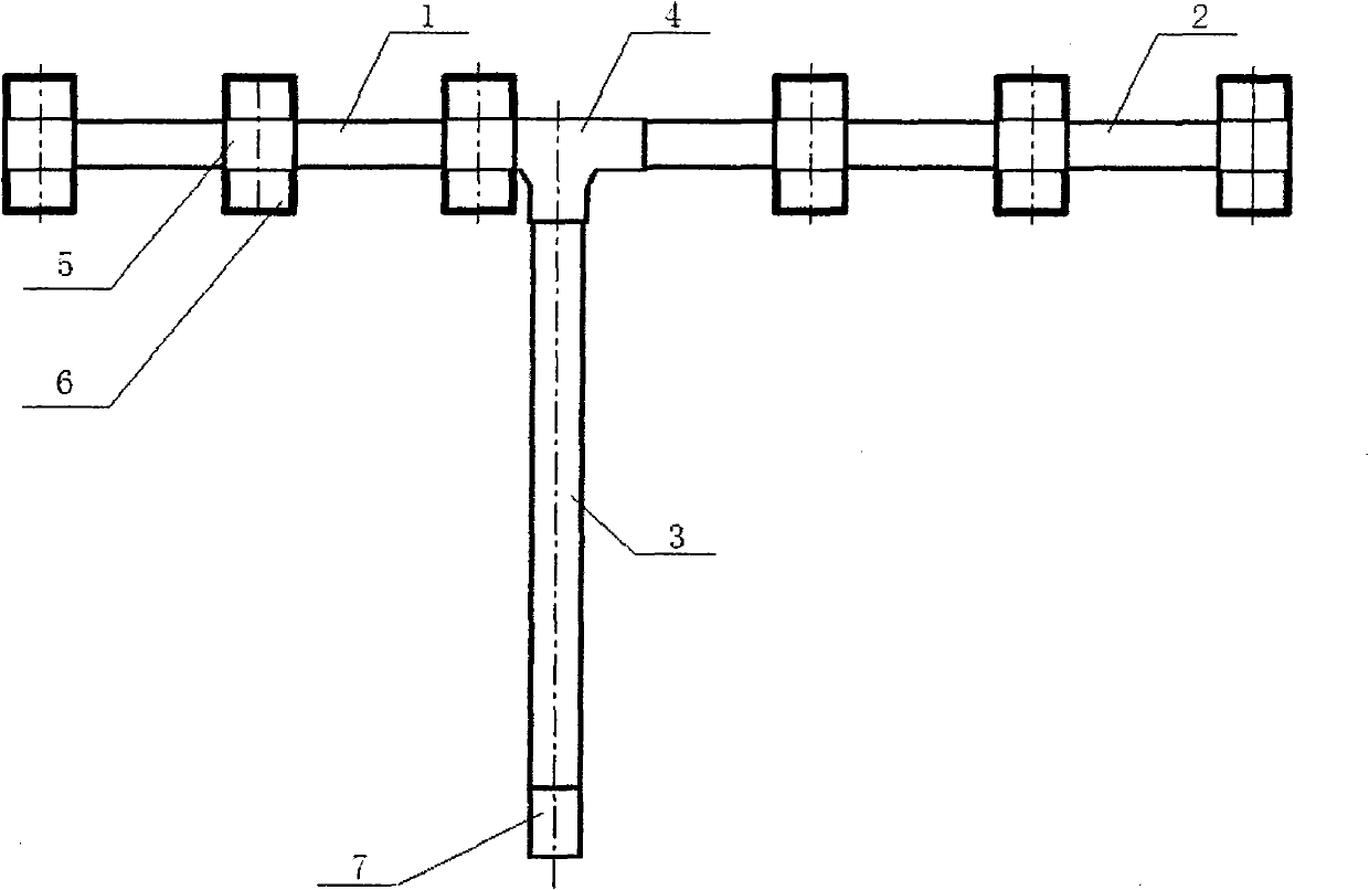
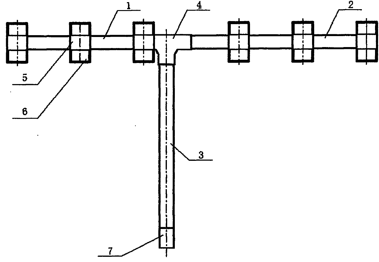
[0022] attached figure 1 It is a structural schematic diagram of a composite material mechanical arm of the present invention, and the structure of the mechanical arm is:

[0023] Three carbon fiber / epoxy composite rods (1, 2, 3) are glued on the carbon fiber / epoxy composite material T-shaped joint (4) to form the main frame T-shaped beam of the mechanical arm. Get six screw holes on the cross bar (1) and cross bar (2) of the beam and connect with six carbon fiber / epoxy composite material saddles (6) by rivets. The saddle (6) is connected with the carbon fiber / epoxy composite material mounting support (5) through adhesive bonding. In order for the composite manipulator to be installed on the transfer robot, it is necessary to install a metal connection joint (7) under the manipulator, and apply J-133 glue to the end of the vertical bar (3) of the T-beam to connect with the metal in the form of glue Connec...

Embodiment 2

[0024] Example 2: Preparation method of composite material manipulator

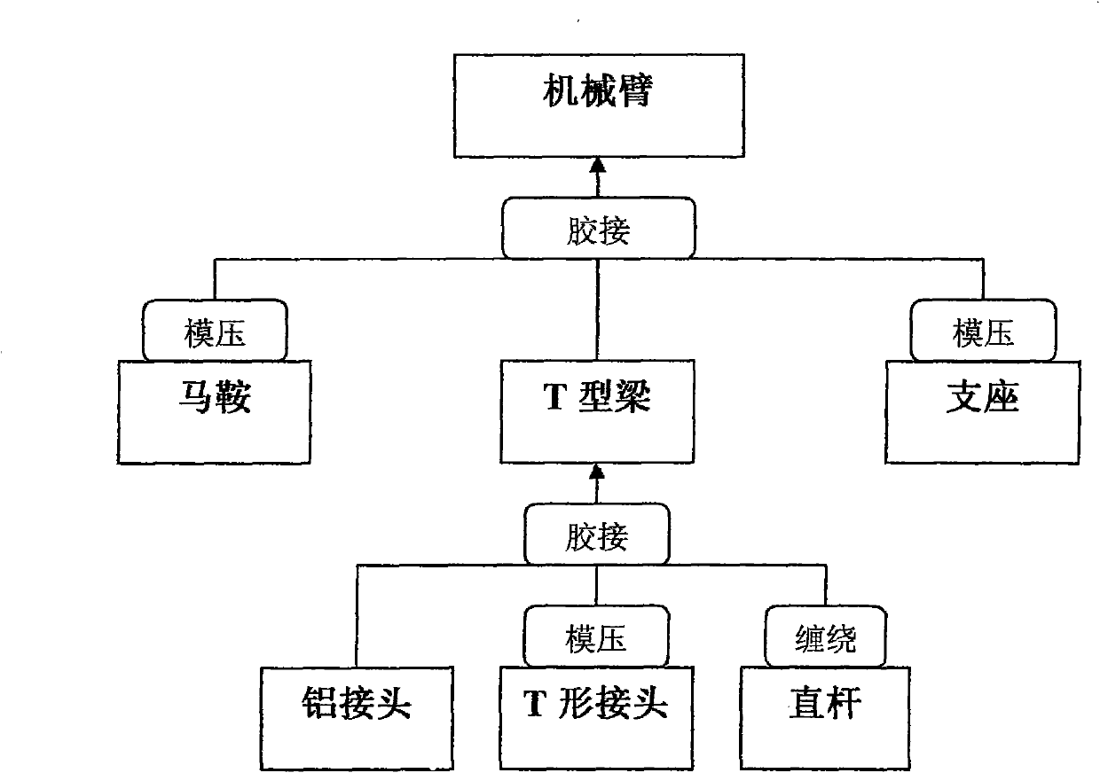
[0025] attached figure 2 It is a schematic diagram of the product structure composition of a composite material manipulator of the present invention. In conjunction with this accompanying drawing, the production process flow of the present invention is described.

[0026] According to the T-shaped joint structure, carbon fiber / epoxy prepreg is used to lay the layers, and the T-shaped joint is formed by composite material joint molding process. Then wind three straight rods at a winding angle of ±30°. Use J-133 glue to glue the three straight rods on the T-shaped joints, and glue the aluminum alloy connection joints to the vertical rods.

[0027] Lay the layers with carbon fiber / epoxy prepreg cloth, and mold the saddle and support by composite material joint molding process. The saddle and support are glued and connected with J-133 glue, and rivet holes are made on the crossbar of the T-beam. The sadd...


PUM


Abstract

The invention discloses a composite material mechanical arm which comprises a T-shaped beam, wherein a saddle (6) is arranged on the T-shaped beam, an installing support (5) is arranged on the saddle, and the beam, the saddle and the installing support are made of carbon fiber/epoxy composite materials. Due to the adoption of the mechanical arm disclosed by the invention, the weight of the traditional mechanical arm is lightened, the rigidity of the mechanical arm can be improved and the flexibility is reduced; especially, when the mechanical arm rapidly rotates, the transmission precision of the mechanical arm can be greatly improved and the use requirement for high-precision transmission is met due to good damping resistance of the composite materials and small vibration of the mechanical arm. The composite material mechanical arm can be used as a transmission arm of an automatic transmission robot in a car assembling line.

Description

technical field [0001] The invention relates to a composite material mechanical arm of an automatic transfer robot used in a car assembly line. Background technique [0002] In the car assembly line, it is necessary to use automatic transfer robots for assembly. The transfer arm of the robot that is routinely used at present is made of aluminum alloy, and this known mechanical arm is heavy in weight, and it is troublesome to manually disassemble the mechanical arm. And the use of this known aluminum alloy manipulator is due to the small rigidity and large deflection of the material itself. During the rapid operation of the manipulator, the manipulator vibrates greatly, which cannot meet the use requirements of precise transmission. [0003] Do not find description or report similar to the present invention at present, also do not collect similar data both at home and abroad. Contents of the invention [0004] In order to solve the problem that the existing aluminum alloy...

Claims


Application Information

Patent Timeline
Patent Type & Authority Applications(China)
IPC IPC(8): B25J9/00
Inventor 梁燕民王建昌叶周军陈磊詹光亮
Owner SHANGHAI COMPOSITES SCI & TECH CO LTD
Why Eureka
Try Eureka